Strain control calculations – MTS Series 793 User Manual
Page 370
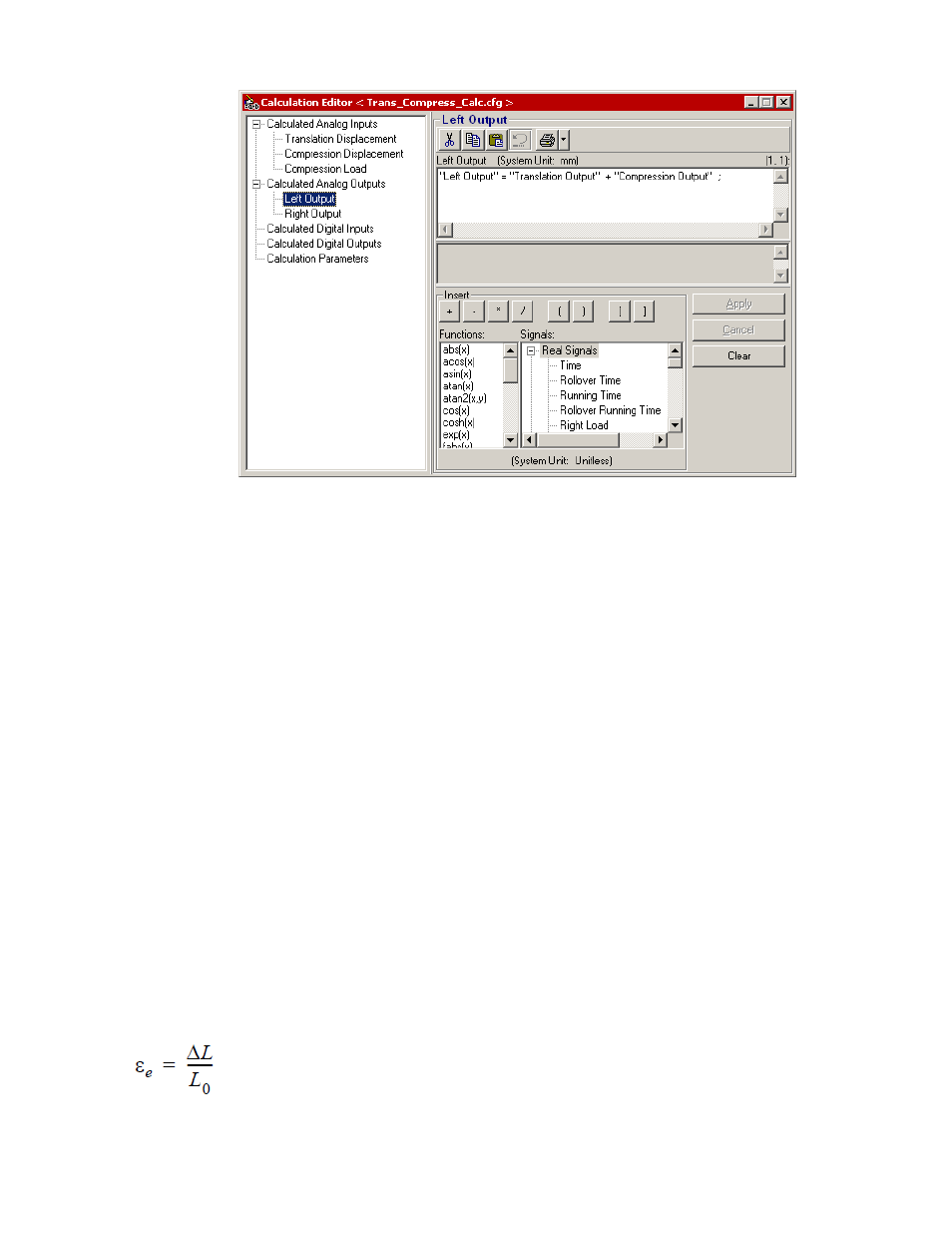
b) Select the calculated output signal from the list for the first servovalve (Left Output), then enter the
required equation in expression window:
“Left Out” = “Translation Output” + “Compression Output”
c) Select the calculated output signal from the list for the second servovalve (Right Output), then enter
the required equation in expression window:
“Right Out” = “Compression Output” - “Translation Output”
Strain Control Calculations
Problem
While testing a metallic specimen in compression, you need to keep deformation constant by keeping the
true strain rate constant.
Solution
Create a true strain control mode by using a calculated true strain feedback signal. This calculated feedback
signal, used by the controller’s summing junction to close the control loop, is a “virtual” signal calculated from
other signals and constants.
Assuming a clip gage is measuring crack opening displacement (COD), create a second calculated signal
called engineering strain (εe). The clip gage measures the change in gage length, then engineering strain is
calculated using the following equation:
Where:
370 MTS Series 793 Control Software
Calculated Signals