15 results: comparing, optimising, logging – Lenze DSD User Manual
Page 388
15
Results: comparing, optimising, logging
15.1
Drawing
388
Lenze · Drive Solution Designer · Manual · DMS 4.2 EN · 12/2013 · TD23
_ _ _ _ _ _ _ _ _ _ _ _ _ _ _ _ _ _ _ _ _ _ _ _ _ _ _ _ _ _ _ _ _ _ _ _ _ _ _ _ _ _ _ _ _ _ _ _ _ _ _ _ _ _ _ _ _ _ _ _ _ _ _ _
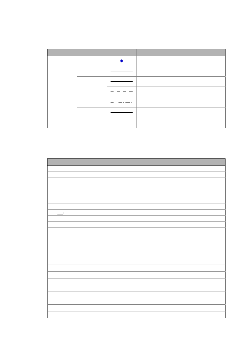
Legend for the representation of the characteristics:
Buttons
Depending on the component, different quantities which can be individually shown or masked out
by means of the following buttons on the upper edge of the profile dialog are shown in the profile
dialog:
Graphics element
Colour
Type
Meaning
Point
Blue
Maximum operating point
Line
Blue
Requirement of the application
Red
Maximum permissible values
Reduced rated values (temperature, height, etc.)
Max. continuous characteristics
Green
Instantaneous PT1 function
Calculated equivalent values
Button
Information
a
Acceleration
α
Angular acceleration
BRK
Setting the brake
CINH
Setting the controller inhibit
f
ch
Switching frequency of the inverter
f
out
Output frequency of the inverter
F
Counterforce
F
Tensile force at the belt
I
Current within the motor, inverter
J
Characteristic of mass inertia
m
Characteristic of the payload mass
s
Translatory traverse path
j
Rotary traverse path
M
Motor, gearbox, application torque
M, n
Speed-torque characteristic of motor/gearbox
M
BRK
Torque curve of the holding brake
M
dyn
Dynamic torque
M
out,G
Output torque of the Lenze gearbox
M
out,K
Output torque of the additional drive element
M
sds
Stationary torque
n
Speed
n
in,G
Drive speed of the Lenze gearbox
n
in,K
Drive speed of the general ratio
n
out,G
Output speed of the Lenze gearbox