1 symbols used, 2 data for the entry, 1 moment of inertia of load – Lenze DSD User Manual
Page 169: 2 friction torque of the load, 3 speed, 4 torque, 7applications
Lenze · Drive Solution Designer · Manual · DMS 4.2 EN · 12/2013 · TD23
169
7
Applications
7.16
General rotary drive
_ _ _ _ _ _ _ _ _ _ _ _ _ _ _ _ _ _ _ _ _ _ _ _ _ _ _ _ _ _ _ _ _ _ _ _ _ _ _ _ _ _ _ _ _ _ _ _ _ _ _ _ _ _ _ _ _ _ _ _ _ _ _ _
7.16.1.1
Symbols used
7.16.2
Data for the entry
7.16.2.1
Moment of inertia of load
7.16.2.2
Friction torque of the load
7.16.2.3
Speed
7.16.2.4
Torque
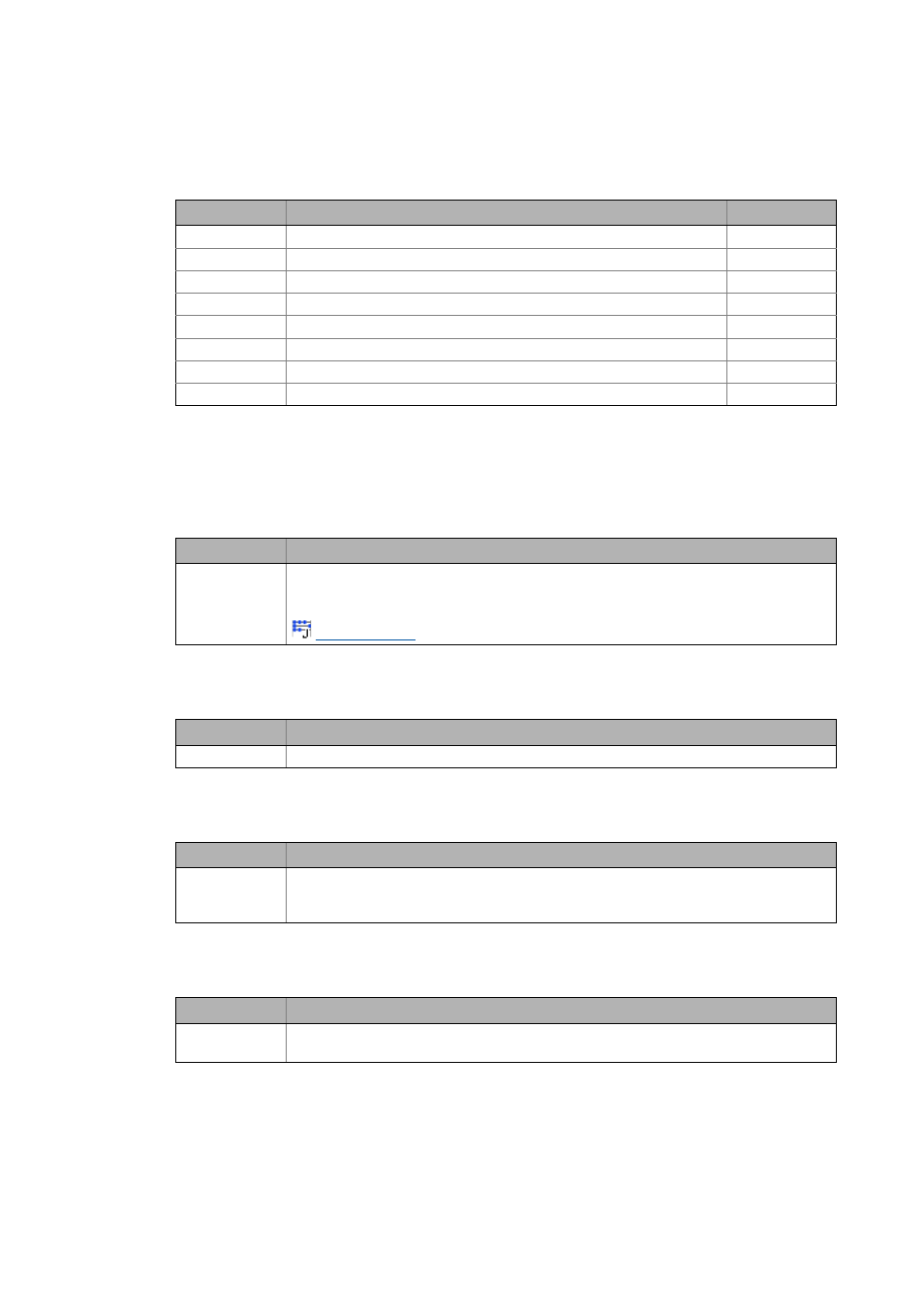
Symbol
Description
Dimension unit
J
L
Moment of inertia of load
kgm
2
M
dyn
Dynamic torque of the application
Nm
M
Total torque
Nm
M
μ,L
Friction torque of the load
Nm
n
Speed of application
rpm
P
Power of the application
W
α
Angular acceleration
rad/s
2
ω
Angular velocity
rad/s
Symbol
Description
J
L
Moment of inertia of load
• Has an impact on the dynamic torque!
• Value can be entered directly or calculated using a inertia calculator.
Symbol
Description
M
μ,L
Friction torque that counteracts the direction of movement.
Symbol
Description
n
Speed required at the output shaft.
• Please note: The speed of the application, not the rated speed of the motor is meant!
• Value is entered in the Motion dimensioning step.
Symbol
Description
m
L
Required torque at the output shaft
• Value is entered in the Motion dimensioning step.