12 components in the dc bus – Lenze DSD User Manual
Page 375
Lenze · Drive Solution Designer · Manual · DMS 4.2 EN · 12/2013 · TD23
375
12
Components in the DC bus
12.6
Brake resistor selection
_ _ _ _ _ _ _ _ _ _ _ _ _ _ _ _ _ _ _ _ _ _ _ _ _ _ _ _ _ _ _ _ _ _ _ _ _ _ _ _ _ _ _ _ _ _ _ _ _ _ _ _ _ _ _ _ _ _ _ _ _ _ _ _
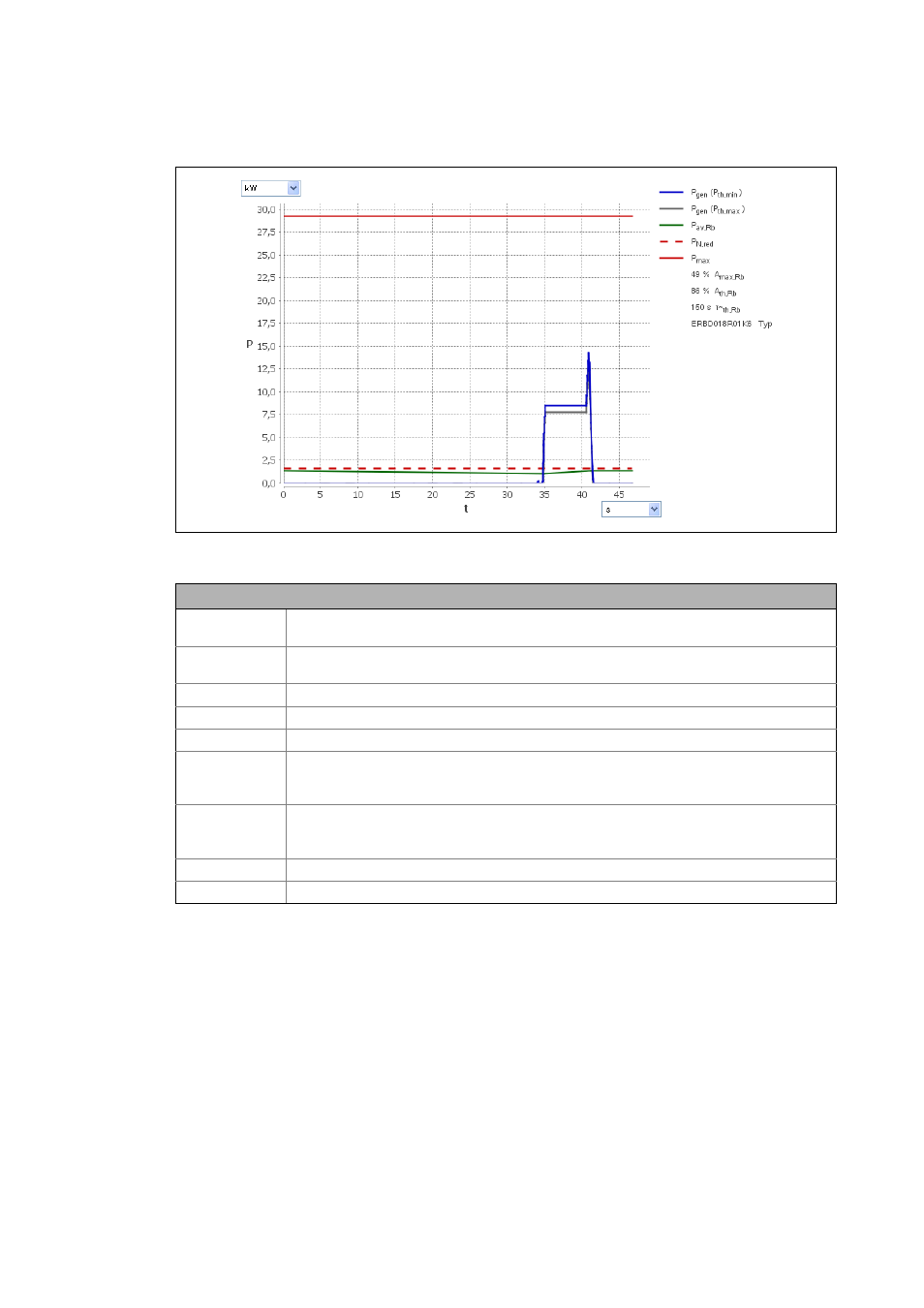
[12-6] Inverter diagram: brake resistor utilisation
Description
P
gen
(P
th,min
)
DC power in generator mode on the brake resistor, assuming ideal efficiency of motor, inverter,
and gearbox.
P
gen
(P
th,max
)
DC power in generator mode on the brake resistor, assuming worst efficiency of motor, inverter,
and gearbox.
P
av,Rb
Average braking power on the brake resistor, considering the thermal time constant (τ
~
th,Brm
)
P
N,red
Continuous power of the brake resistor
P
max
Peak power of the brake resistor
A
max,Rb
Max. utilisation of the brake resistor
Possible message: The max. utilisation of the equivalent resistance is xxx %. Thus the limit value
of 100 % is exceeded.
A
th,Rb
Thermal utilisation of the brake resistor
Possible message: The permanent utilisation of the equivalent resistance is xxx %. Thus the limit
value of 100 % is exceeded.
τ
~
th,Rb
Thermal time constant for checking the brake resistor
Type
Brake resistor type