8motion design – Lenze DSD User Manual
Page 265
Lenze · Drive Solution Designer · Manual · DMS 4.2 EN · 12/2013 · TD23
265
8
Motion design
8.2
MotionDesigner
_ _ _ _ _ _ _ _ _ _ _ _ _ _ _ _ _ _ _ _ _ _ _ _ _ _ _ _ _ _ _ _ _ _ _ _ _ _ _ _ _ _ _ _ _ _ _ _ _ _ _ _ _ _ _ _ _ _ _ _ _ _ _ _
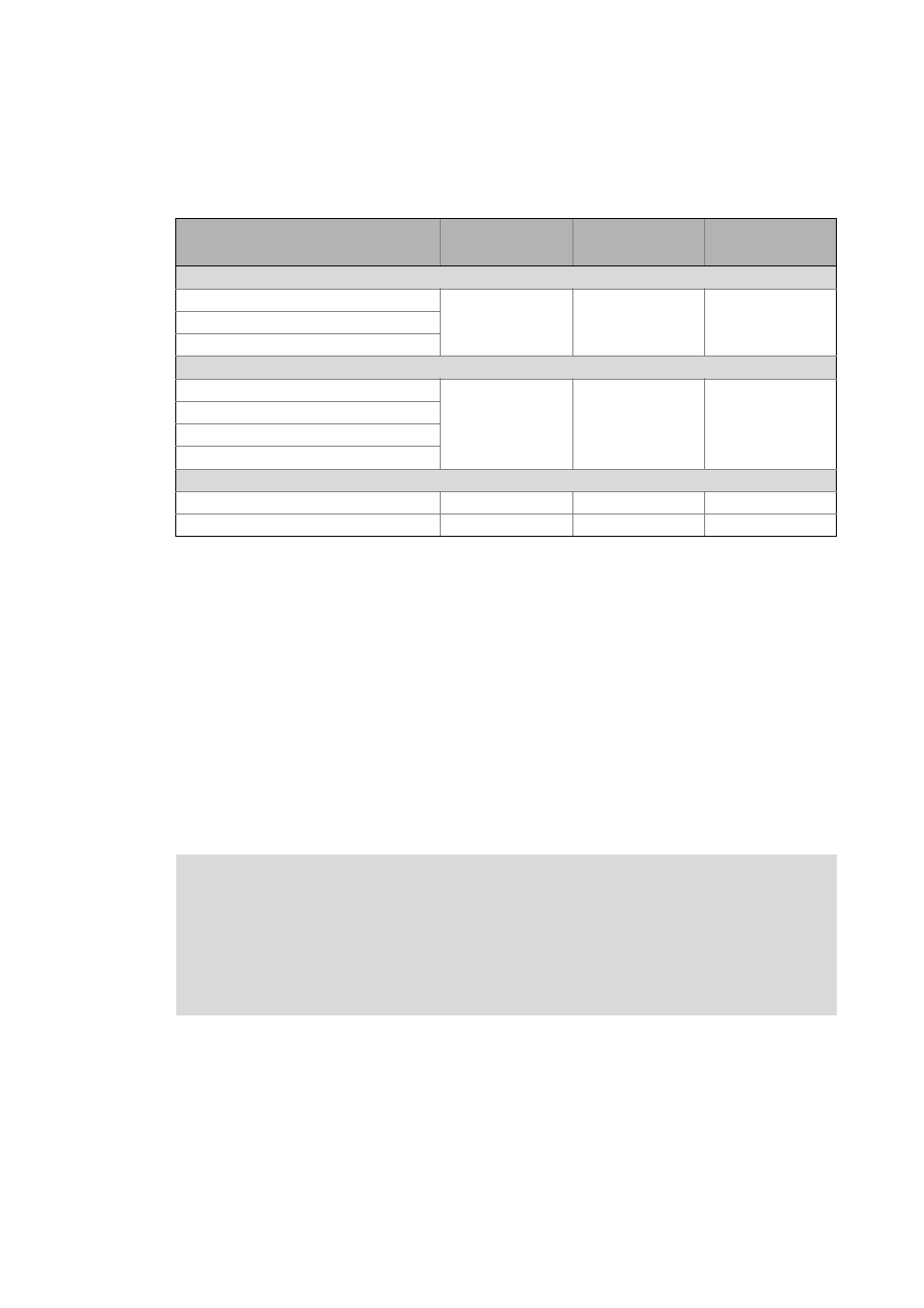
• The table below provides guide values for minimum acceleration and deceleration times. If the
values fall below these values, the behaviour of the control system of the drive must be checked
in addition.
VFCPlus
SLVC
SC
t
acc,set
/t
dec,set
t
acc,set
/t
dec,set
t
acc,set
/t
dec,set
Servo inverters
i700
< 100 ms
–
< 50 ms
Servo Drives 9400
Inverter Drives 8400 TopLine
Frequency inverter
Inverter Drives 8400 BaseLine
< 100 ms
< 500 ms
< 50 ms
Inverter Drives 8400 StateLine
Inverter Drives 8400 HighLine
Inverter Drives 8400 TopLine
Decentralised inverters
Inverter Drives 8400 motec
< 100 ms
< 500 ms
–
Inverter Drives 8400 protec
< 100 ms
< 500 ms
< 50 ms
The following conditions must be complied with:
• t
r,set
> t
dyn,min
• t
f,set
> t
dyn,min
VFCPlus
Voltage frequency control
SLVC
Sensorless vector control
SC
Servo control
t
acc,set
Acceleration time - setpoint
t
acc,act
Acceleration time - actual value
t
dec,set
Deceleration time - setpoint
t
dec,act
Deceleration time - actual value
t
dyn,min
Dynamic acceleration and deceleration time that the control system of the inverter is able to realise at
least
Note!
Without a specific feedforward control of the required acceleration torque within the in-
verter, these control-related delay times are to be taken into consideration.
If the actual times are lower than the delay times, a control-related system consideration
on the basis of empirical checks (e. g. on a test configuration) or by an appropriate simu-
lation has to be carried out in addition to the drive dimensioning with the DSD.