12 components in the dc bus – Lenze DSD User Manual
Page 376
12
Components in the DC bus
12.6
Brake resistor selection
376
Lenze · Drive Solution Designer · Manual · DMS 4.2 EN · 12/2013 · TD23
_ _ _ _ _ _ _ _ _ _ _ _ _ _ _ _ _ _ _ _ _ _ _ _ _ _ _ _ _ _ _ _ _ _ _ _ _ _ _ _ _ _ _ _ _ _ _ _ _ _ _ _ _ _ _ _ _ _ _ _ _ _ _ _
12.6.6.2
Brake resistor on the power supply module or regenerative power supply module
The following power supply modules and regenerative power supply modules have an integrated
brake transistor to which brake resistors can be connected to.
• 9400 power supply module
• 9400 regenerative power supply module
• i700 power supply module
The simulation of device-internal monitoring functions serves for the evaluation of the power de-
mand by DSD and the determination of the utilisation of the brake resistor.
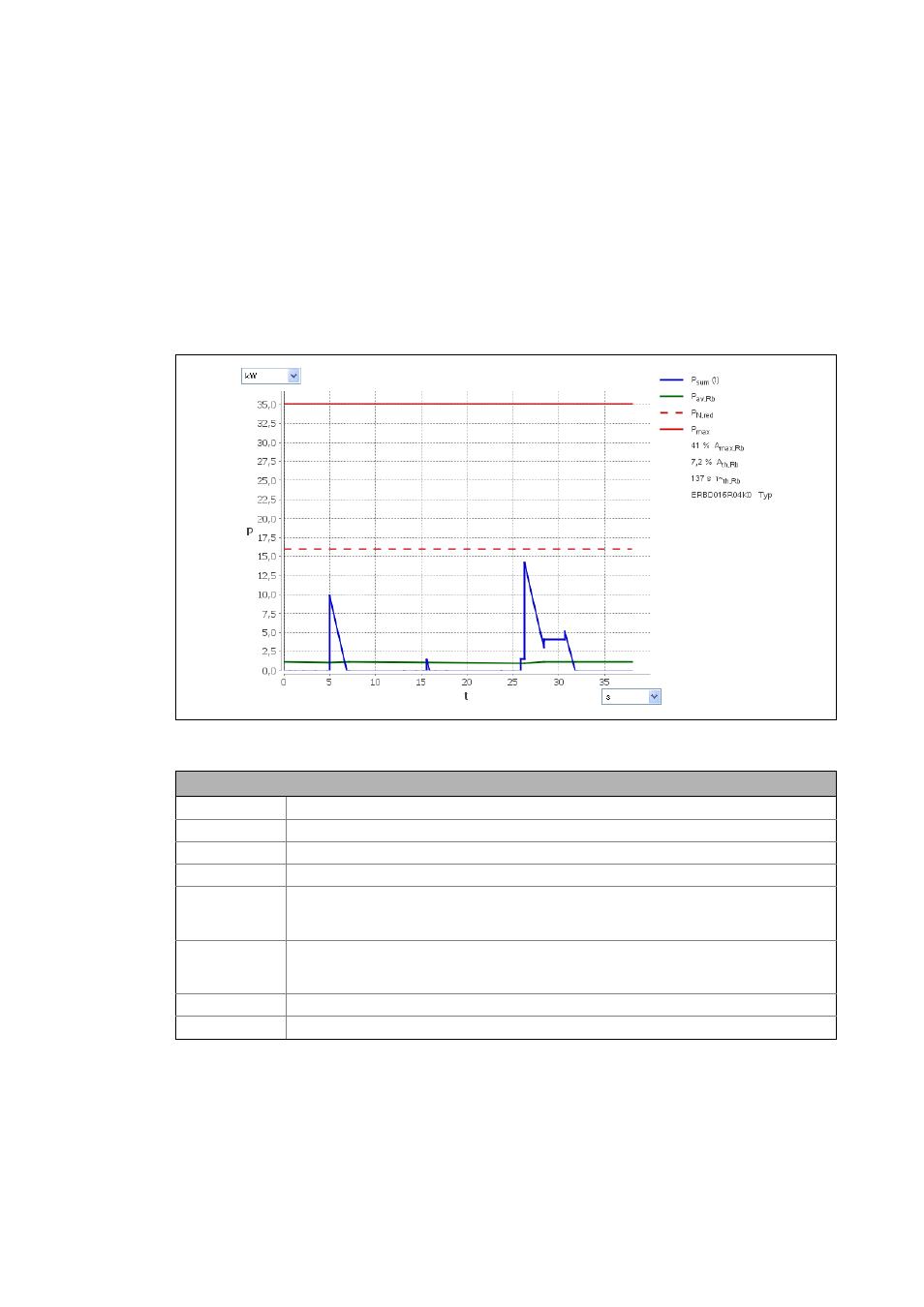
[12-7] Power supply module or regenerative power supply module diagram: brake resistor utilisation
Description
P
sum
(t)
Total power in generator mode in the DC bus over time
P
av,Rb
Average braking power on the brake resistor, considering the thermal time constant (τ
~
th,Brm
)
P
N,red
Continuous power of the brake resistor
P
max
Peak power of the brake resistor
A
max,Rb
Max. utilisation of the brake resistor
Possible message: The max. utilisation of the equivalent resistance is xxx %. Thus the limit value
of 100 % is exceeded.
A
th,Rb
Thermal utilisation of the brake resistor
Possible message: The permanent utilisation of the equivalent resistance is xxx %. Thus the limit
value of 100 % is exceeded.
τ
~
th,Rb
Thermal time constant for checking the brake resistor
Type
Brake resistor type