5 overcurrent operation for inverter drives 8400, 11 drive dimensioning – Lenze DSD User Manual
Page 351
Lenze · Drive Solution Designer · Manual · DMS 4.2 EN · 12/2013 · TD23
351
11
Drive Dimensioning
11.6
Inverters
_ _ _ _ _ _ _ _ _ _ _ _ _ _ _ _ _ _ _ _ _ _ _ _ _ _ _ _ _ _ _ _ _ _ _ _ _ _ _ _ _ _ _ _ _ _ _ _ _ _ _ _ _ _ _ _ _ _ _ _ _ _ _ _
11.6.1.5
Overcurrent operation for Inverter Drives 8400
The inverters are designed for a temporary overcurrent. The utilisation by a defined, cyclic operation
is determined via the "Ixt" monitoring function. The I×t function consists of two moving averages
which are checked in parallel:
• A short-time moving average of the apparent motor current for a pulse utilisation.
• A continuous moving average of the apparent motor current for a continuous utilisation.
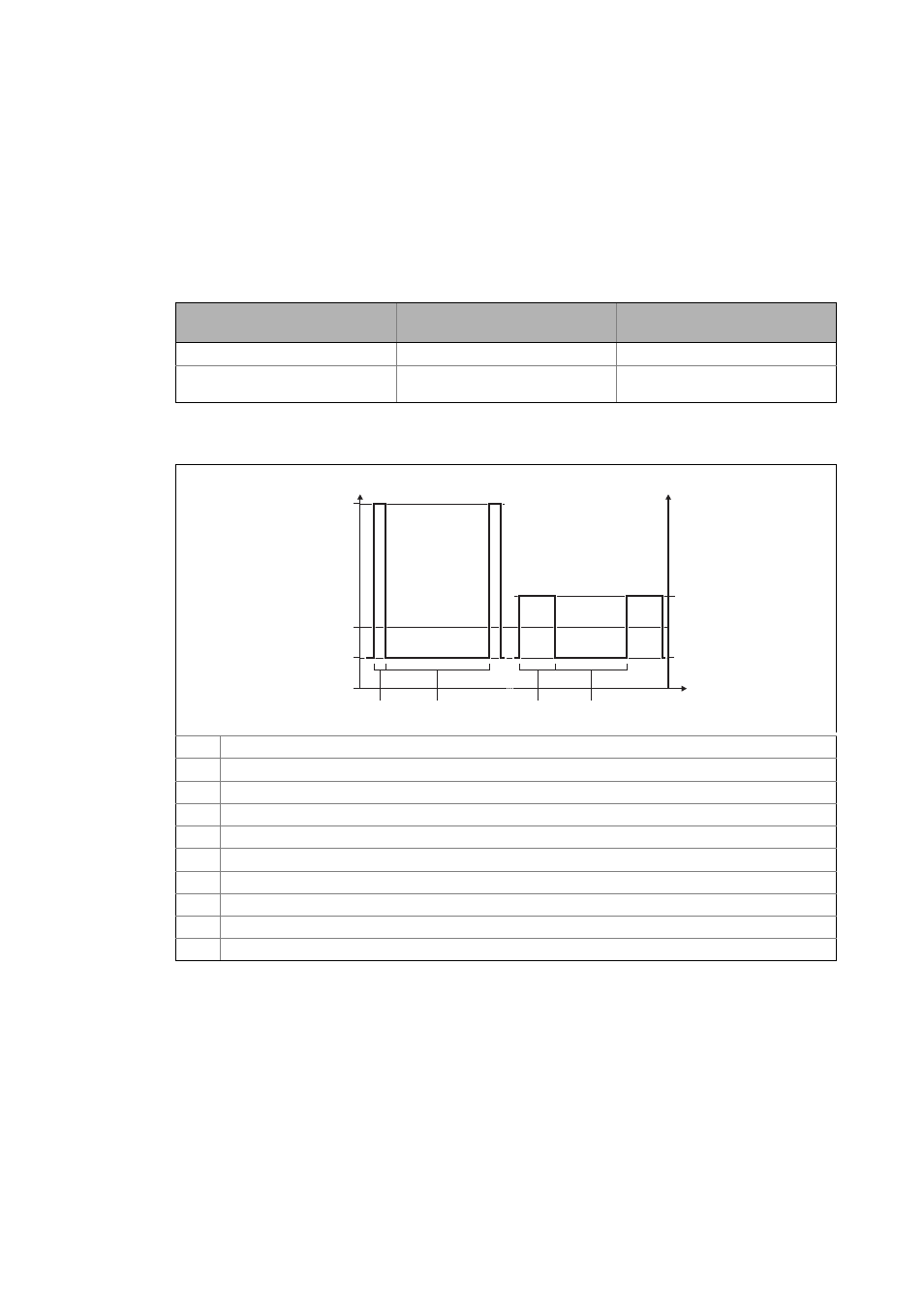
The characteristics of typical load functions and the simulation of the "Ixt" function are shown in the
following illustration:
[11-22] Overcurrent capability for Inverter Drives 8400 at 45 °C
Type of utilisation
Utilisation cycle
Condition for the monitoring func-
tion
Pulse utilisation
15 s
I
rated,out
> 160 %
Permanent utilisation
180 s
The monitoring function is switched
on continuously.
Pulse utilisation (cycle of 15 s)
Peak current
Limited current during the recovery time
Δt
1
Load with peak current (typically 3 s)
Δt
2
Recovery time with limited current (typically 12 s)
Permanent utilisation (cycle of 180 s)
Peak current
Limited current during the recovery time
Δt
3
Load with peak current (typically 60 s)
Δt
4
Recovery time with limited current (typically 120 s)
t
0
100
2
0
1
I
[%]
N,out
3
Dt
1
Dt
2
Dt
3
Dt
4