1 symbols used, 2 data for the entry, 1 radius, payload – Lenze DSD User Manual
Page 171: 7applications
Lenze · Drive Solution Designer · Manual · DMS 4.2 EN · 12/2013 · TD23
171
7
Applications
7.17
Rotary table drive
_ _ _ _ _ _ _ _ _ _ _ _ _ _ _ _ _ _ _ _ _ _ _ _ _ _ _ _ _ _ _ _ _ _ _ _ _ _ _ _ _ _ _ _ _ _ _ _ _ _ _ _ _ _ _ _ _ _ _ _ _ _ _ _
Torque of the application
[7-164] Equation 3: Torque of the application
A consideration of the angle of tilt for the stationary torque currently is not yet included. For this the
torque has to be determined for each angle position.
Power of the application
[7-165] Equation 4: Power of the application
Tip!
Further equations to complete the calculations required for an application can be found in
the chapter "
".
7.17.1.1
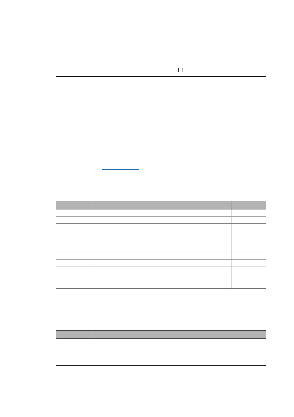
Symbols used
7.17.2
Data for the entry
7.17.2.1
Radius, payload
M
App
M
dyn
M
μ,L
ω
ω
-------
⋅
+
=
P
App
M
App
n 2 π
⋅
60
-----------
⋅ ⋅
=
Symbol
Description
Dimension unit
J
add
Moment of inertia of the rotary table
kgm
2
J
sum
Total moment of inertia
kgm
2
m
L
Mass of payload
kg
M
dyn
Dynamic torque
Nm
M
App
Required torque of the application
Nm
M
μ,L
Friction torque of the load
Nm
n
Speed of application
rpm
P
App
Power of the application
W
r
L
Radius of movement of the payload
m
α
Angular acceleration
rad/s
2
ω
Angular velocity
rad/s
Symbol
Description
r
L
Radius of movement of the payload
• Path from the centre of rotation of the table to the supporting point of the payload.
• This radius is relevant for the inertia proportion of the payload. For the calculation one has to
think of the payload as a point mass. The mass of the payload is entered when the motion
profile is created.