3 combining lenze products, 7applications – Lenze DSD User Manual
Page 191
Lenze · Drive Solution Designer · Manual · DMS 4.2 EN · 12/2013 · TD23
191
7
Applications
7.21
Dimension the multi-axis system
_ _ _ _ _ _ _ _ _ _ _ _ _ _ _ _ _ _ _ _ _ _ _ _ _ _ _ _ _ _ _ _ _ _ _ _ _ _ _ _ _ _ _ _ _ _ _ _ _ _ _ _ _ _ _ _ _ _ _ _ _ _ _ _
7.21.3
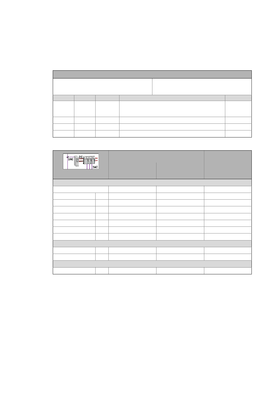
Combining Lenze products
Overview of combinability of inverters and additional components with power supply modules or
regenerative power supply modules.
Equations for the calculation of the effective moment of inertia for linear motors
Axis A
Axis B
Symbol Description
Dimension unit
-
-
s Length which is the basis of the number of encoder incre-
ments.
(e.g. pole spacing or total length)
m
-
-
2τ
pole pair
Pole spacing of the permanent magnets, pole pair width
m
-
-
J Mass moment of inertia
kg m
2
-
-
m Mass of carriage
kg
Supply module
Regenerative power sup-
ply module
E94APN
I
DC
= 10 ... 245 A
P
DC
= 5.6 ... 137 kW
E70ACPSx
I
N,DC
= 30/60 A
E94xx
P
DC,mot
= 15/30 kW
P
DC,gen
= 7.5/15 kW
Servo inverters
Single Drive 9400
0.37 … 11 kW
15 … 30 kW
45 … 55 kW
75 … 370 kW
Multi Drive 9400
8400 TopLine
i700
Frequency inverter
8400 StateLine
8400 HighLine
Additional component
Brake resistor ERBx
The combination is possible without restrictions.
The combination is possible with restrictions:
The EMC protection of the device is not effective in the DC-bus connection. Check whether EMC measures
are required for the entire DC-bus connection or machine.
The braking circuit of the drive axis cannot be dimensioned in the DSD. DSD only dimensions a central brak-
ing circuit as it is for example contained in the 9400 power supply module.
If alternative or additional brake choppers are to be set in the drive axes, these braking circuits have to be
checked manually.
No or no sufficient starting current limitation available. Special measures have to be taken. Please contact
your Lenze sales partner.
The combination is not reasonable since the power range of the power supply module or the regenerative
power supply module is too low. If the DSD does not display an active message when the module is selected,
you can use this combination.
zp
Integer
s
2τ
Pole pair
------------------------
=
J
m
zp 2τ
Pole pair
⋅
2π
-----------------------------------
2
⋅
=