2 servo inverters, 10 structure of the drive axis, 3 drive concept 296 – Lenze DSD User Manual
Page 296
10
Structure of the drive axis
10.3
Drive concept
296
Lenze · Drive Solution Designer · Manual · DMS 4.2 EN · 12/2013 · TD23
_ _ _ _ _ _ _ _ _ _ _ _ _ _ _ _ _ _ _ _ _ _ _ _ _ _ _ _ _ _ _ _ _ _ _ _ _ _ _ _ _ _ _ _ _ _ _ _ _ _ _ _ _ _ _ _ _ _ _ _ _ _ _ _
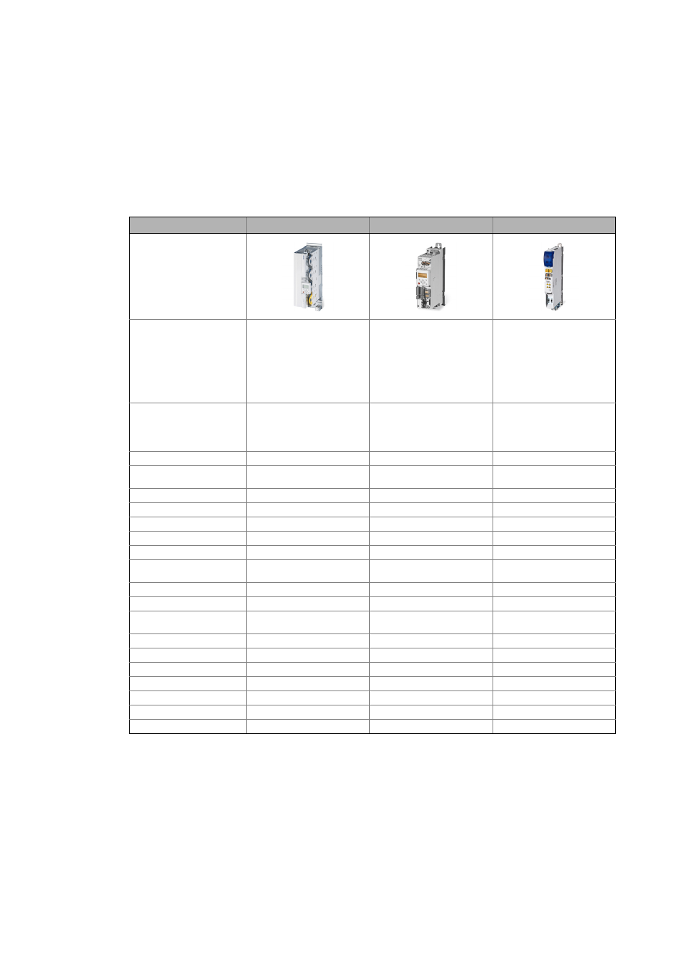
10.3.4.2
Servo inverters
Servo inverters are highly dynamic current-controlled systems for speed, torque, or position control.
They are characterised by a high speed accuracy, a great torque setting range, and a high overload
capacity. For the operation a speed feedback is always required.
• Position-controlled systems are suitable for drive tasks as e.g. positioning, electronic gearbox or
electronic cam.
Servo Drives 9400
8400 TopLine
i700
Illustration
Short description
Intelligent servo inverter for single-
axis and multi-axis applications,
function block structure that can be
freely interconnected, activation via
digital inputs/outputs and/or field-
bus, modular safety functions, inno-
vative backplane system, pluggable
memory chip for the parameter set
Servo inverters for synchronous and
asynchronous servo motors, suitable
for speed and position-controlled
applications and positioning appli-
cations, multi encoder input, option-
ally with integrated safety
functions, fieldbus communication,
pluggable memory chip for the pa-
rameter set
Servo inverter for single-axis and
multi-axis applications, compact de-
sign and connection system, flexible
motor control for synchronous and
asynchronous motors, multi-axis
system with central supply
Voltage range/power range
Single Drive:
3 AC 180 … 550 V: 0.37 … 370 kW
DC 260 … 775 V: 0.37 … 370 kW
Multi Drive:
DC 260 … 775 V: 0.37 … 15 kW
1 AC 180 … 264 V: 0.25 … 2.2 kW
3 AC 320 … 550 V: 0.37 … 45 kW
Power supply module:
3 AC 320 … 528 V
DC 260 … 775 V
Axis module:
DC 260 … 775 V: 0.75 … 15 kW
Approvals
CE, UL508C
CE, UL, GOST-R, RoHS
CE, UL508C
Permissible power systems
TN, TT, IT
TN, TT, IT,
RoHS-compliant
TN, TT, IT
Switching frequencies
1, 2, 4, 8, 16 kHz
2, 4, 8, 16 kHz
4, 8, 16 kHz
Mechanical design
Built-in unit
Push-through technique
–
(up to 15 kW)
Cold plate technique
–
(up to 22 kW)
Installation backplane
(SingleDrive up to 11 kW)
(MultiDrive up to 15 kW)
–
–
Enclosure
IP 20
IP 20
IP 20
Operation in generator mode
Integrated brake resistor
(SingleDrive, power supply modules)
External brake transistor
–
–
–
Regenerative
–
–
Control types
V/f control
Vector control (encoderless)
–
Synchronous motors (encoderless)
–
–
Servo control