7 selection table, 11 drive dimensioning – Lenze DSD User Manual
Page 319
Lenze · Drive Solution Designer · Manual · DMS 4.2 EN · 12/2013 · TD23
319
11
Drive Dimensioning
11.2
Motor selection
_ _ _ _ _ _ _ _ _ _ _ _ _ _ _ _ _ _ _ _ _ _ _ _ _ _ _ _ _ _ _ _ _ _ _ _ _ _ _ _ _ _ _ _ _ _ _ _ _ _ _ _ _ _ _ _ _ _ _ _ _ _ _ _
11.2.7
Selection table
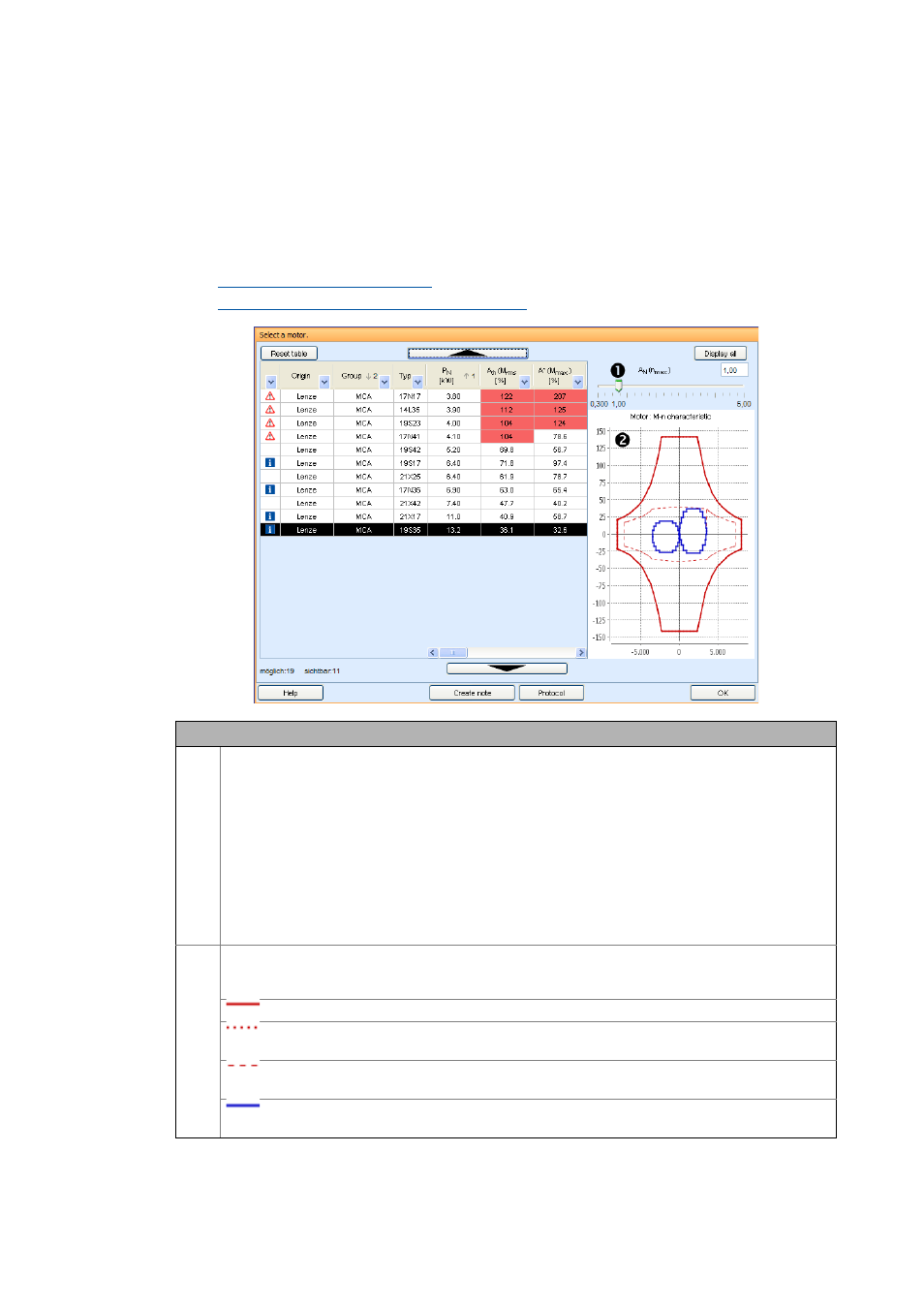
The motor selection table presents the parameters of the motors available. Here, it is distinguished
between preview values and further parameters.
• A basic description of the selection table and tools for a quick selection of suitable components
can be found here:
Structure of the selection tables
Sorting and filtering results in selection tables
Description
Slider for optimally utilising the rated speed
• For the calculation of the required torque the motor inertia is taken into consideration. The gearbox ratio
is calculated so that the rated speed (applicable to all applications except for winders) of the motor is as-
sumed as the max. speed.
• The sliders of winders with asynchronous or synchronous motors have a default setting of "2".
• By means of the slider you can optimally adapt the motor:
• Value = 1: rated speed
• Values > 1: speed greater than rated speed (field weakening).
• Values < 1: speed smaller than rated speed.
• Lenze setting for winding applications:
• Asynchronous motors: 2.0
• Synchronous motors: 1.0
Torque-speed characteristic of the motor.
• The represented characteristic refers to the motor-inverter combination. The inverter family selected in
the Drive concept dimensioning step is used.
Characteristic curve of the motor.
Calculated characteristic curve of the motor.
• For most motors, measured characteristic curves are stored in DSD.
S1 characteristic of the motor.
• Vertical characteristic: rated motor speed.
Torque-speed characteristic of the application requirement.
• By means of the slider you can adapt the characteristic.