5 integrated brake transistor utilisation, 1 brake transistor in the inverter, 12 components in the dc bus – Lenze DSD User Manual
Page 372
12
Components in the DC bus
12.6
Brake resistor selection
372
Lenze · Drive Solution Designer · Manual · DMS 4.2 EN · 12/2013 · TD23
_ _ _ _ _ _ _ _ _ _ _ _ _ _ _ _ _ _ _ _ _ _ _ _ _ _ _ _ _ _ _ _ _ _ _ _ _ _ _ _ _ _ _ _ _ _ _ _ _ _ _ _ _ _ _ _ _ _ _ _ _ _ _ _
12.6.5
Integrated brake transistor utilisation
12.6.5.1
Brake transistor in the inverter
The following inverters have an integrated brake transistor to which brake resistors can be connect-
ed to.
• Servo Drives 9400
• Inverter Drives 8400
• Inverter Drives 8400 protec
• Inverter Drives 8400 motec
The simulation of device-internal monitoring functions serves for the evaluation of the power de-
mand by DSD and the determination of the utilisation of the brake transistor.
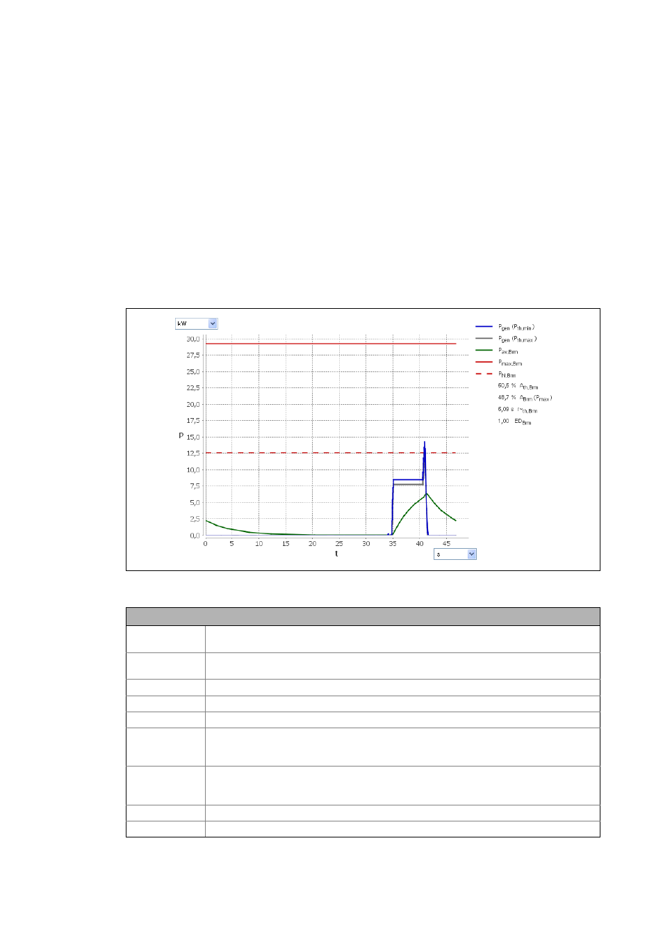
[12-4] Inverter diagram: utilisation of the integrated brake transistor
Description
P
gen
(P
th,min
)
DC power in generator mode on the brake transistor, assuming ideal efficiency of motor, gear-
box, and inverter.
P
gen
(P
th,max
)
DC power in generator mode on the brake transistor, assuming worst efficiency of motor, gear-
box, and inverter.
P
av,Brm
Average braking power on the brake transistor, considering the thermal time constant (τ
~
th,Brm
)
P
max,Brm
Peak braking power of the brake transistor
P
N,Brm
Continuous braking power of the brake transistor
A
th,Brm
Thermal utilisation of the brake transistor.
• Possible message: The permanent utilisation of the brake transistor is xxx %. Thus the limit
value of 100 % is exceeded.
A
Brm
(P
max
)
Utilisation of the brake transistor relative to the peak braking power
• Possible message: The max. utilisation of the brake chopper is xxx %. Thus the limit value of
100 % is exceeded.
τ
~
th,Brm
Thermal time constant for checking the brake transistor
ED
Brm
Relative operating time of the brake resistor (pulse-pause ratio)