10 structure of the drive axis, 10 .3 dri ve con ce pt – Lenze DSD User Manual
Page 307
10
Structure of the drive axis
10
.3
Dri
ve con
ce
pt
Lenze ·
Dri
ve
Soluti
on
Desi
gner ·
M
anual
· DM
S
4.
2
EN
·
12/2013 ·
TD23
30
7
_ _
_ _
_ _
_ _
_ _
_ _
_ _
_ _
_ _
_ _
_ _
_ _
_
_ _
_ _
_ _
_ _
_ _
_ _
_ _
_ _
_ _
_ _
_ _
_ _
_ _
_ _
_ _
_ _
_ _
_ _
_ _
_
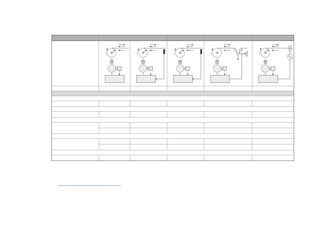
10.3.8
Selection help: Control types for winding drive systems
Tension control (M)
Tension control (M)
1)
Tension control (n)
1)
Dancer position control (n)
Velocity control (n)
Winder control mode
Traversing motor control
Open-loop torque control
Closed-loop torque control
Closed-loop speed control
Closed-loop speed control
Open-loop speed control
Control system
SC
Rewinder/unwinder
+
+
+
+
+
VFCplus without encoder
Rewinder/unwinder
–
–
–
0
0
SLVC
Rewinder
+
–
–
0
+
Unwinder
–
–
–
–
–
VFCplus with encoder
Rewinder
0
–
–
0
0
Unwinder
–
–
–
0
0
VFCplus eco
Rewinder/unwinder
–
–
–
–
–
+ Well-suited
SC Servo control
0 Suitable with restrictions
VFCplus V/f control
– Not suitable
VFCplus eco V/f control with energetically optimised field injection in the partial load operational range
1)
Comparison of tension-controlled winder control modes
SLVC Sensorless
vector
control
v
F
M
3~
Inverter
n, M
r
v
F
n, M
r
M
3~
Inverter
M = f(F, r)
n = f(v, r)
F
act
v
F
n, M
r
M
3~
Inverter
M = f(F, r)
n = f(v, r)
F
act
v
F
F~F
G
F
G
M
3~
n, M
Inverter
Actual
position
v
F
M
3~
n, M
r
v
act
Inverter
M = f(F, r)
n = f(v, r)