2 additional drive element, 3 feedback, 4 electromechanical brake – Lenze DSD User Manual
Page 284: 10 structure of the drive axis
10
Structure of the drive axis
10.1
Mechanical drive axis
284
Lenze · Drive Solution Designer · Manual · DMS 4.2 EN · 12/2013 · TD23
_ _ _ _ _ _ _ _ _ _ _ _ _ _ _ _ _ _ _ _ _ _ _ _ _ _ _ _ _ _ _ _ _ _ _ _ _ _ _ _ _ _ _ _ _ _ _ _ _ _ _ _ _ _ _ _ _ _ _ _ _ _ _ _
10.1.2
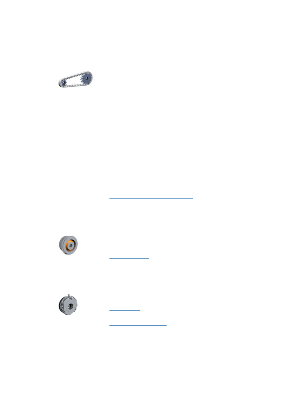
Additional drive element
Make this selection if the application includes an additional drive element.
10.1.3
Feedback
Make this selection if the application includes a feedback.
10.1.4
Electromechanical brake
Make this selection if the application includes an electromechanical brake.
• If you do not select a Lenze gearbox and additional drive element the mo-
tor is directly connected to the application.
• DSD can simulate a user-definable mechanical ratio (additional drive
component) with a toothed belt, flat belt, V-belt, chain, gear, or an indi-
vidual gearbox.
• The additional drive element can be placed between the application and
the motor or between the application and the Lenze gearbox.
• Additional drive element in winding applications.
• Toothed belts as mechanical transmission elements between the
drive and the winder are very well-suited because they have low fric-
tion and good damping characteristics.
• Cardan shafts as axial coupling are suitable for big reels in center
winding machines if the reels must be moved together with their ped-
estals for the winding process.
• Axial couplings (e.g. cardan shafts) between the winding shaft and the
motor or the gearbox output must be dimensioned in a low backlash
manner.
• The data for the additional drive element are entered in a later dimen-
sioning step.
Selection of an additional drive element
• For drives with a servo control a feedback system is required. A servo con-
trol without a feedback system cannot be dimensioned in the DSD.
• The feedback system is selected in a later dimensioning step.
• The electromechanical brake is only checked if a parameter has been cre-
ated for the brake in the motion profile.
• The electromechanical brake is selected in a later dimensioning step.