3 possible speed controller amplification factors, 11 drive dimensioning – Lenze DSD User Manual
Page 323
Lenze · Drive Solution Designer · Manual · DMS 4.2 EN · 12/2013 · TD23
323
11
Drive Dimensioning
11.2
Motor selection
_ _ _ _ _ _ _ _ _ _ _ _ _ _ _ _ _ _ _ _ _ _ _ _ _ _ _ _ _ _ _ _ _ _ _ _ _ _ _ _ _ _ _ _ _ _ _ _ _ _ _ _ _ _ _ _ _ _ _ _ _ _ _ _
11.2.8.3
Possible speed controller amplification factors
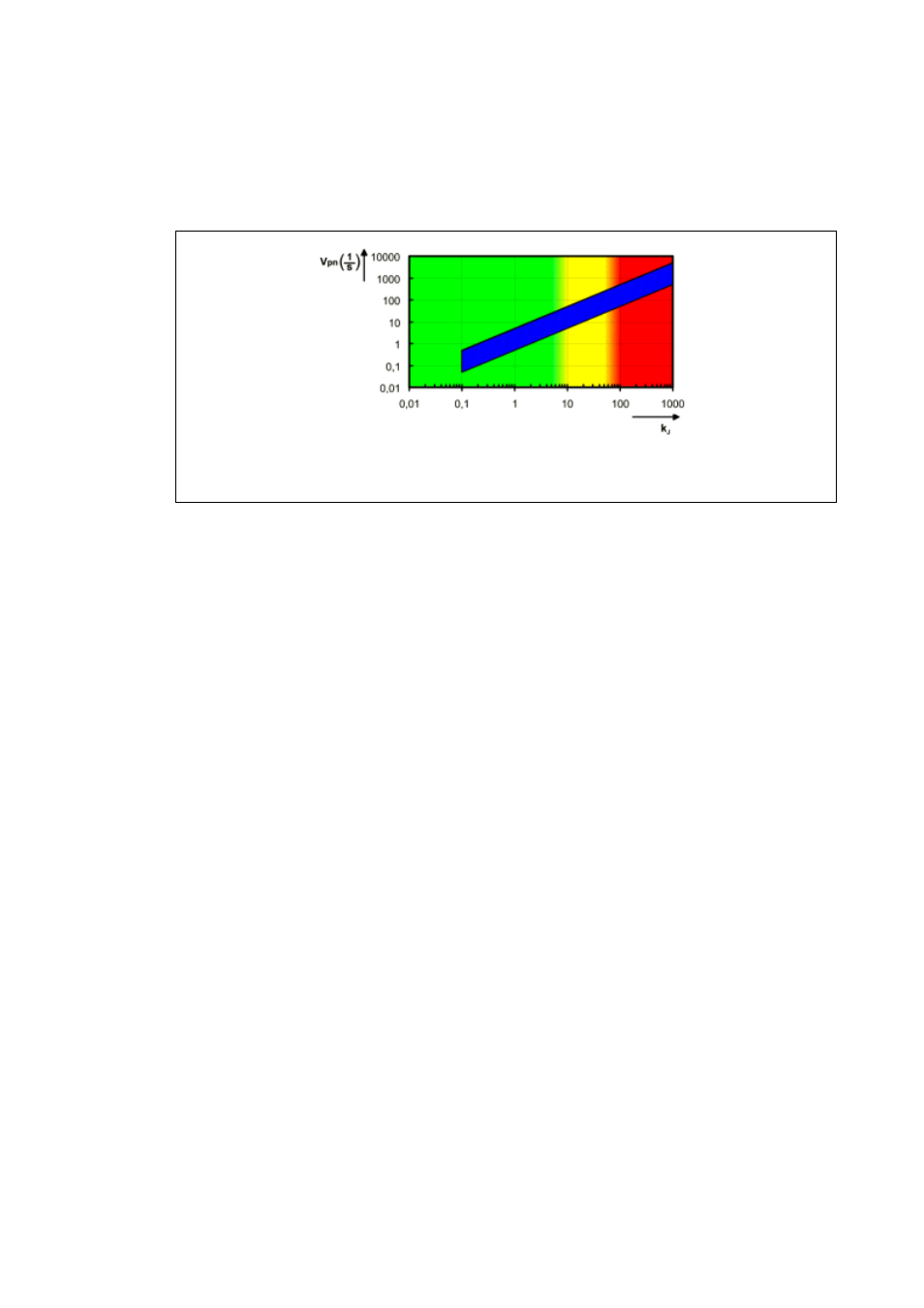
The following illustration shows the theoretically possible speed controller amplification factors for
cyclic load alternation (rough guide values):
[11-7] Theoretically possible speed controller amplification factors as a function of K
J
From a control-related perspective, a great moment of inertia, and therefore a great k
J
factor re-
quires a great amplification factor V
p
in the speed controller.
• Because of backlash and elasticity in the gearbox, standard controller structures can only reach
certain k
J
factors in the practical control-loop implementations.
• If these values are exceeded, they lead to a reduced control response or even instability, par-
ticularly with regard to cyclic load alternations.
• If there are no load alternations, the stable control range moves up towards higher k
J
factors.
11.2.8.4
Optimising controls with a high load-matching factor
If high load-matching factors k
J
cannot be avoided for speed-controlled or angle-controlled systems,
a backlash-free or low-backlash mechanical transmission should be used. Toothed belts are well-
suited for this purpose due to their good damping features.
Further measures for optimising controls with high k
J
factors are:
• Torque feedforward controls for dynamic phases.
• Specific adaptations, e. g. of the amplification factor V
p
within the speed controller, as a func-
tion of the moments of inertia which in turn can also be variable.
• Speed controller as a P controller.
• Adjustment of the actual speed value filter to load moment of inertia.
• Use of low-jerk motion profiles that do not exert any, or only a low incitation on vibratory sys-
tems.
green = OK
yellow = observe boundary conditions
red = inclination to instability