3 calculation of the mains current, Calculation of the mains current, 9mains and environment – Lenze DSD User Manual
Page 281
Lenze · Drive Solution Designer · Manual · DMS 4.2 EN · 12/2013 · TD23
281
9
Mains and environment
9.3
Calculation of the mains current
_ _ _ _ _ _ _ _ _ _ _ _ _ _ _ _ _ _ _ _ _ _ _ _ _ _ _ _ _ _ _ _ _ _ _ _ _ _ _ _ _ _ _ _ _ _ _ _ _ _ _ _ _ _ _ _ _ _ _ _ _ _ _ _
9.3
Calculation of the mains current
DSD calculates the effective mains current on the basis of the DC bus power for the following devic-
es:
• Inverter for a single-axis application
• Power supply module or regenerative power supply module for a multi-axis system
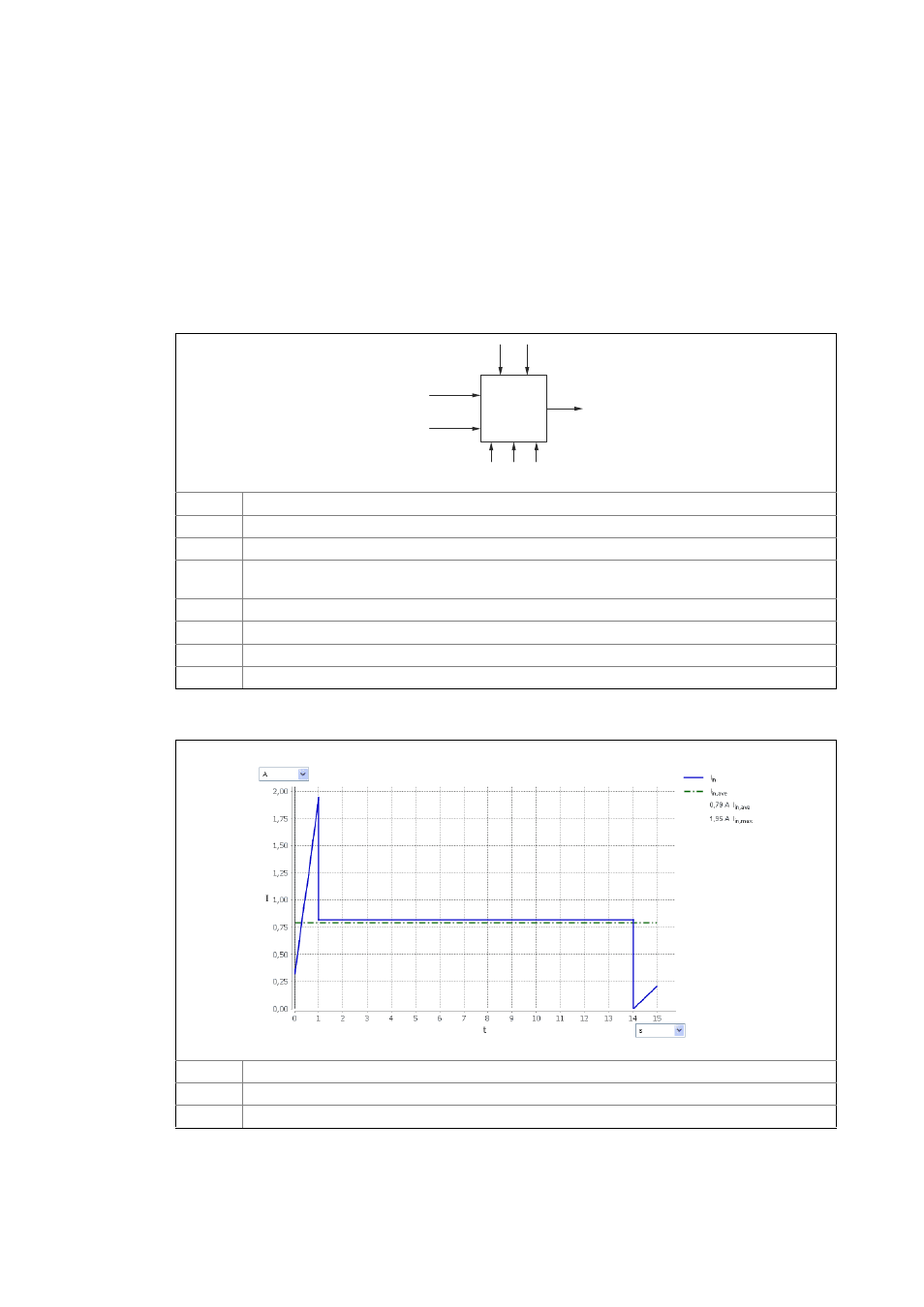
The diagram shows variables which are of importance and which are taken into consideration for
the calculation.
[9-1]
Diagram: calculation of the mains current in DSD
[9-2]
Diagram inverter/power supply module: mains current
P
DC
DC bus power
P
DC
< 0 Query: DC bus power < 0
U Mains voltage
3 AC
1 AC
Three-phase or one-phase mains
I
in
(t) Effective mains current, time curve
With or without a mains choke (only for inverters for control cabinet installation)
Inverters for control cabinet installation or decentralised inverters
Factor for undervoltage: -10 %
P
DC
P
< 0
DC
U
I (t)
in
3 AC
1 AC
I
in
Time curve of the effective mains current
I
in,ave
Average effective mains current
I
in,max
Maximum effective mains current