2 combining drive axes, 7applications – Lenze DSD User Manual
Page 185
Lenze · Drive Solution Designer · Manual · DMS 4.2 EN · 12/2013 · TD23
185
7
Applications
7.21
Dimension the multi-axis system
_ _ _ _ _ _ _ _ _ _ _ _ _ _ _ _ _ _ _ _ _ _ _ _ _ _ _ _ _ _ _ _ _ _ _ _ _ _ _ _ _ _ _ _ _ _ _ _ _ _ _ _ _ _ _ _ _ _ _ _ _ _ _ _
7.21.2
Combining drive axes
7.21.2.1
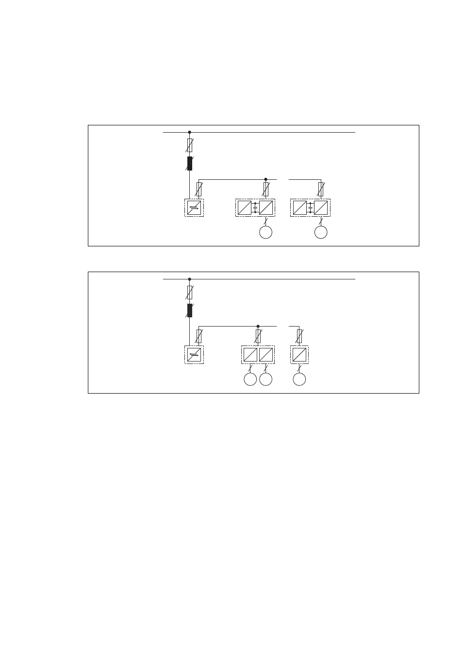
Central mains supply via regenerative power supply module
[7-181] Inverter with rectifier and inverted rectifier on central mains supply via regenerative power supply module
[7-182] Single-axis and double-axis devices (e.g. i700) on central mains supply via regenerative power supply module
Excessive electrical energy (braking energy) is made available to the drive axes in the DC-bus con-
nection or is fed to the mains via the regenerative power supply module.
• The arrangement can be dimensioned in the DSD.
• The drive axes can be each dimensioned separately in the DSD.
• In the "Dimension the multi-axis system" application you combine the drive axes and dimen-
sion the regenerative power supply module.
• DSD calculates the entire power requirement. For operation in generator mode it is checked
whether the braking power needs to be dissipated via an additional brake resistor if the re-
generative power of the regenerative power supply module is not sufficient.
3 AC
DC bus
M
3~
2
2
3
3
M
3~
...
...
2
3
3
=
~
=
~
=
~
=
~
=
~
3 AC
DC bus
M
3~
2
2
3
3
...
...
2
3
=
~
=
~
M
3~
3
=
~
=
~
M
3~
3