6 spindle drive, 1 calculations, Spindle drive – Lenze DSD User Manual
Page 100: Calculations, 7applications
7
Applications
7.6
Spindle drive
100
Lenze · Drive Solution Designer · Manual · DMS 4.2 EN · 12/2013 · TD23
_ _ _ _ _ _ _ _ _ _ _ _ _ _ _ _ _ _ _ _ _ _ _ _ _ _ _ _ _ _ _ _ _ _ _ _ _ _ _ _ _ _ _ _ _ _ _ _ _ _ _ _ _ _ _ _ _ _ _ _ _ _ _ _
7.6
Spindle drive
The vast majority of positioning systems require linear movements. If a rotating drive is used, the
rotation of the motor has to be converted into a linear movement. The speeds that can be achieved,
and therefore the dynamics of the positioning process and the repeat accuracy, and thus the quality
of the positioning process to a great extent are defined by the mechanics.
Characteristics of a spindle drive
• A motor (if required with a gearbox) actuates a spindle that moves the spindle slide with the
load.
• Spindles are used for a high positioning accuracy and low speeds. The positioning path is limit-
ed.
• For the accurate adjustment of limit stops and the accurate positioning of the workpiece in pro-
duction machines, spindles are generally used.
7.6.1
Calculations
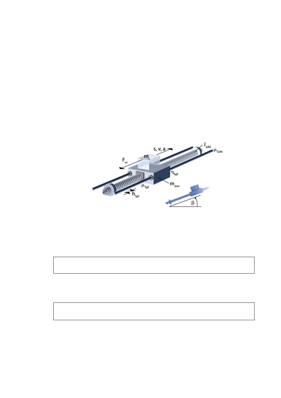
For a spindle drive according to the drawing the following applies:
First the leadscrew pitch is converted to a resulting radius.
[7-51] Equation 1: Resulting radius of the spindle
The moment of inertia of the spindle can be determined if its geometry is known.
• The following, for instance, applies to a solid cylinder:
[7-52] Equation 2: Moment of inertia of the spindle
r
Res
h
Spl
2000 π
⋅
---------------------
=
J
add
π
32 1000
4
⋅
---------------------------
d
Spl
4
l
Spl
ρ
⋅
⋅
⋅
=