2 electrical drive axis, 2 inverter with dc supply (multi-axis application), Electrical drive axis – Lenze DSD User Manual
Page 285: 10 structure of the drive axis
Lenze · Drive Solution Designer · Manual · DMS 4.2 EN · 12/2013 · TD23
285
10
Structure of the drive axis
10.2
Electrical drive axis
_ _ _ _ _ _ _ _ _ _ _ _ _ _ _ _ _ _ _ _ _ _ _ _ _ _ _ _ _ _ _ _ _ _ _ _ _ _ _ _ _ _ _ _ _ _ _ _ _ _ _ _ _ _ _ _ _ _ _ _ _ _ _ _
10.2
Electrical drive axis
10.2.1
Inverter with mains supply (single-axis application)
Make this selection if the inverter is directly connected to the supply system.
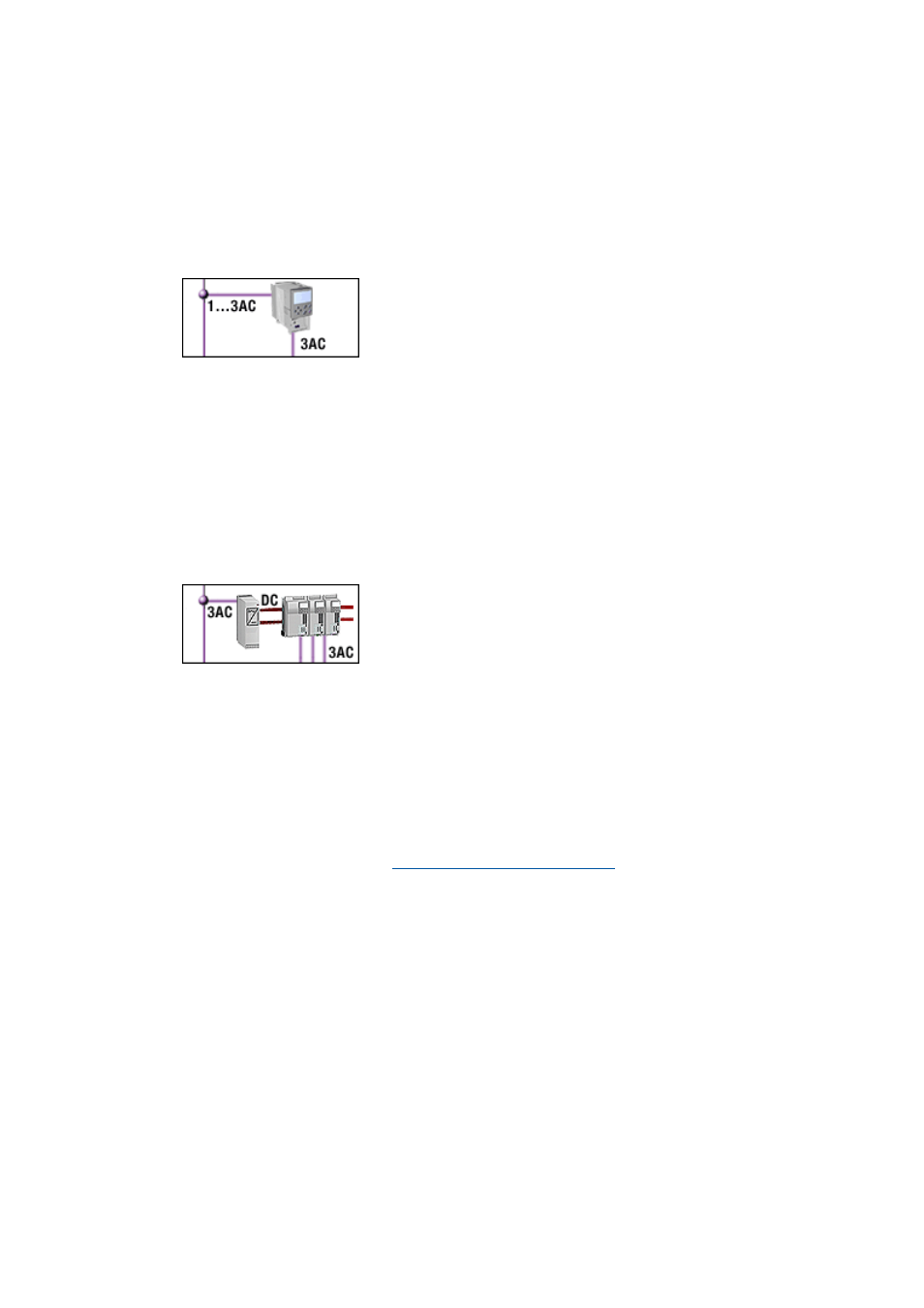
10.2.2
Inverter with DC supply (multi-axis application)
Make this selection if the drive axis is part of a multi-axis system or if it is supposed to feed back
excessive energy back to the mains due to high regenerative power. This selection enables you to
make efficient use of regenerative power in the drive system.
• Operation of an inverter connected directly to the AC system
(single-axis operation).
• There is no coupling via the DC bus.
• Suitable for single drive axes without energy-efficient use of
the regenerative power.
• DSD only offers inverters that combine supply (rectifiers) and in-
verters in one device and that are suitable for a direct connection
to the AC system.
• The connection to the AC system is made via a central power
supply unit (power supply module or regenerative power supply
module). The inverter is connected to the supply unit via the DC
bus.
• The supply via the supply system and the electrical braking sys-
tem can be configured in the "dimension multi-axis system" ap-
plication. For this purpose, the DSD projects of the drive axes are
loaded into the application.
• DSD offers inverters
• that combine supply (rectifiers) and inverters in one device
and come with a DC-bus connection,
• that do not have a supply (rectifiers) but only the inverter.
They are only suitable for being connected to the DC-bus.