2 utilisation, 5 selection of components, 12 components in the dc bus – Lenze DSD User Manual
Page 367
Lenze · Drive Solution Designer · Manual · DMS 4.2 EN · 12/2013 · TD23
367
12
Components in the DC bus
12.5
Selection of components
_ _ _ _ _ _ _ _ _ _ _ _ _ _ _ _ _ _ _ _ _ _ _ _ _ _ _ _ _ _ _ _ _ _ _ _ _ _ _ _ _ _ _ _ _ _ _ _ _ _ _ _ _ _ _ _ _ _ _ _ _ _ _ _
12.4.2
Utilisation
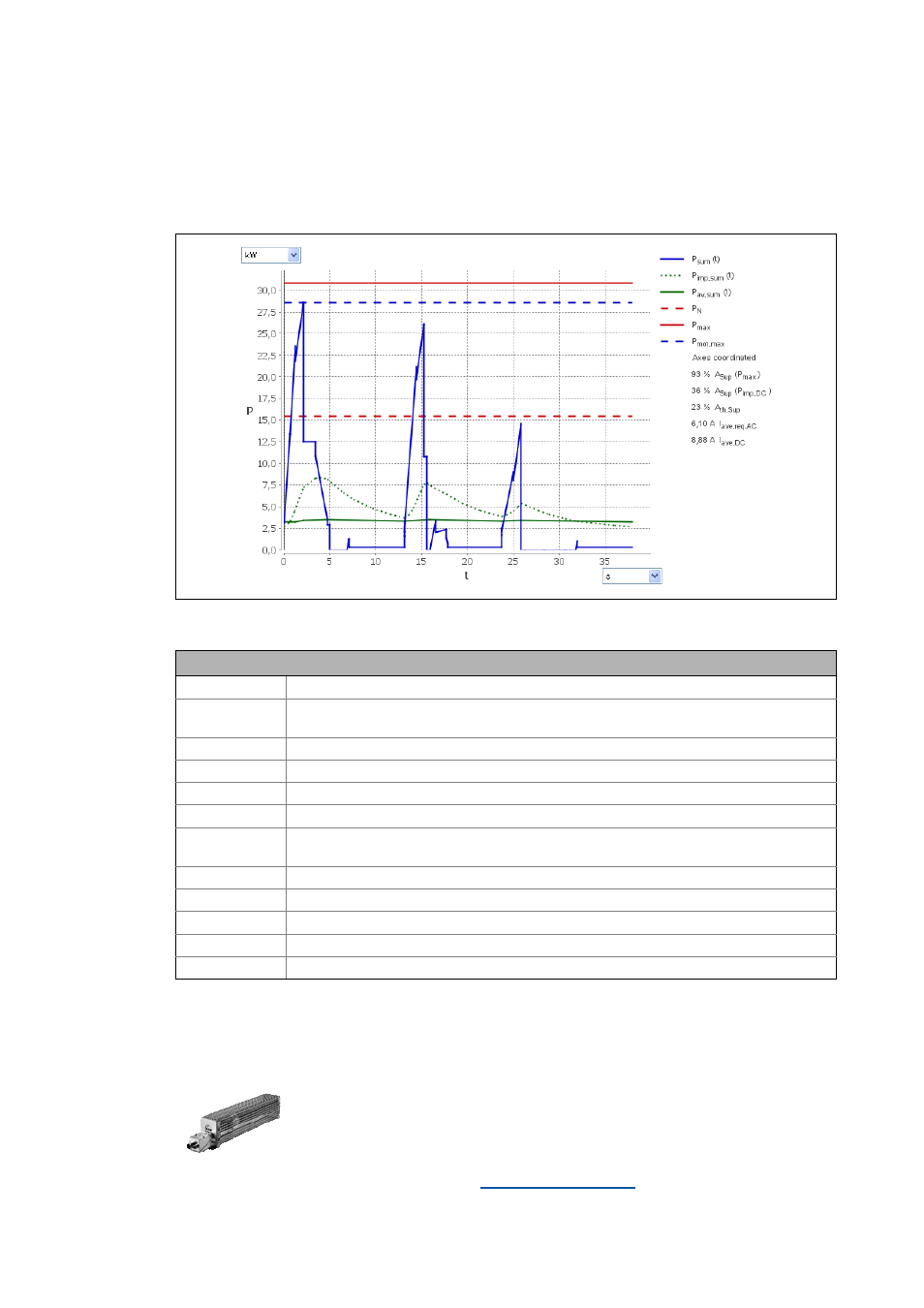
The simulation of device-internal monitoring functions serves for the evaluation of the power de-
mand by DSD and the determination of the utilisation of the power supply module.
[12-3] Power supply module i700 diagram: utilisation
12.5
Selection of components
Description
P
sum
(t)
Total power in the DC bus over time
P
imp,sum
(t)
Pulse power in motor mode in the DC bus
• Relevant for the short-time thermal utilisation of the power supply module
P
av,sum
(t)
Average power in the DC bus
P
rated
Permissible DC continuous power in supply mode
P
max
Max. permissible power in regenerative feedback mode
P
mot,max
Demand of the max. DC bus power in motor mode
Axes coordinated Movement of drive axes
• Axes can be coordinated or uncoordinated
A
th,Sup
Thermal utilisation of the power supply module
A(P
imp,DC
)
Short-time thermal utilisation of the power supply module
A
sup
(P
max
)
Utilisation of the power supply module, relative to the max. power in the DC bus
I
ave,req,AC
Average AC power demand of the device (for cable dimensioning)
I
ave,DC
Average DC power demand of the device (for cable dimensioning)
DSD detects automatically whether an electrical braking system is required.
If the "Components selection" dimensioning step is displayed, the applica-
tion does not need an electrical braking system. The selection is optional.
• If this selection is activated, a brake resistor can be selected in the next
dimensioning step.