Yaskawa MP940 Reference Manual User Manual
Page 361
Troubleshooting
MotionSuite™ MP940 Machine Controller Reference Manual
10-8
A.10
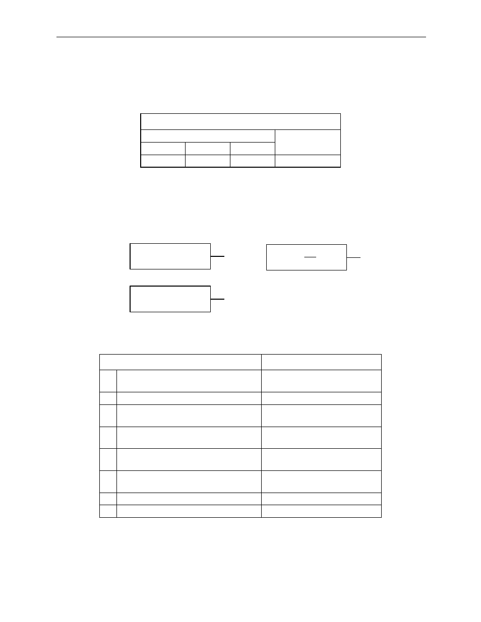
A.10 is the overcurrent or heat sink overheat alarm display. The alarm output
appears below.
Note:
The
indicates the output transistor is ON; the x indicates the output transistor is OFF (alarm
state).
Status when Alarm Occurred
Note:
E ~ H may cause alarms in 1.5kW ~ 3kW servo amplifiers.
Alarm Output
Alarm Code Output
ALM Output
ALO1
ALO2
ALO3
x
x
x
Cause
Remedy
A
Wiring grounded between servo ampli-
fier and servo motor.
Check and correct the wiring.
B
Servo motor U, V, or W phase grounded. Replace servo motor.
C
Circuit board (1PEB) defective.
Power transistor defective.
Replace servo amplifier.
D
Current feedback circuit, power transis-
tor, DB circuit, or circuit board defective.
Replace servo amplifier.
E
The ambient temperature of the servo
amplifier exceeds 55ºC.
Lower the ambient temperature
to below 55ºC.
F
Poor airflow around heat sink.
Make the mounting, peripheral
space as per manual.
G
Fan stopped.
Replace servo amplifier.
H
Running above rated load.
Lighten load.
Alarm occurrs during
motor operation
A,B,D,E,
F,G,H
C, D
C
Alarm occurrs at power
ON
Alarm occurrs when servo
ON signal (S-ON) is ON