Yaskawa MP940 Reference Manual User Manual
Page 141
Mechatrolink Function
MotionSuite™ MP940 Machine Controller Reference Manual
4-50
Pn50A.0~Pn50.B, Pn511
Parameters
Name
Setting
Content
Factory
Setting
—
—
—
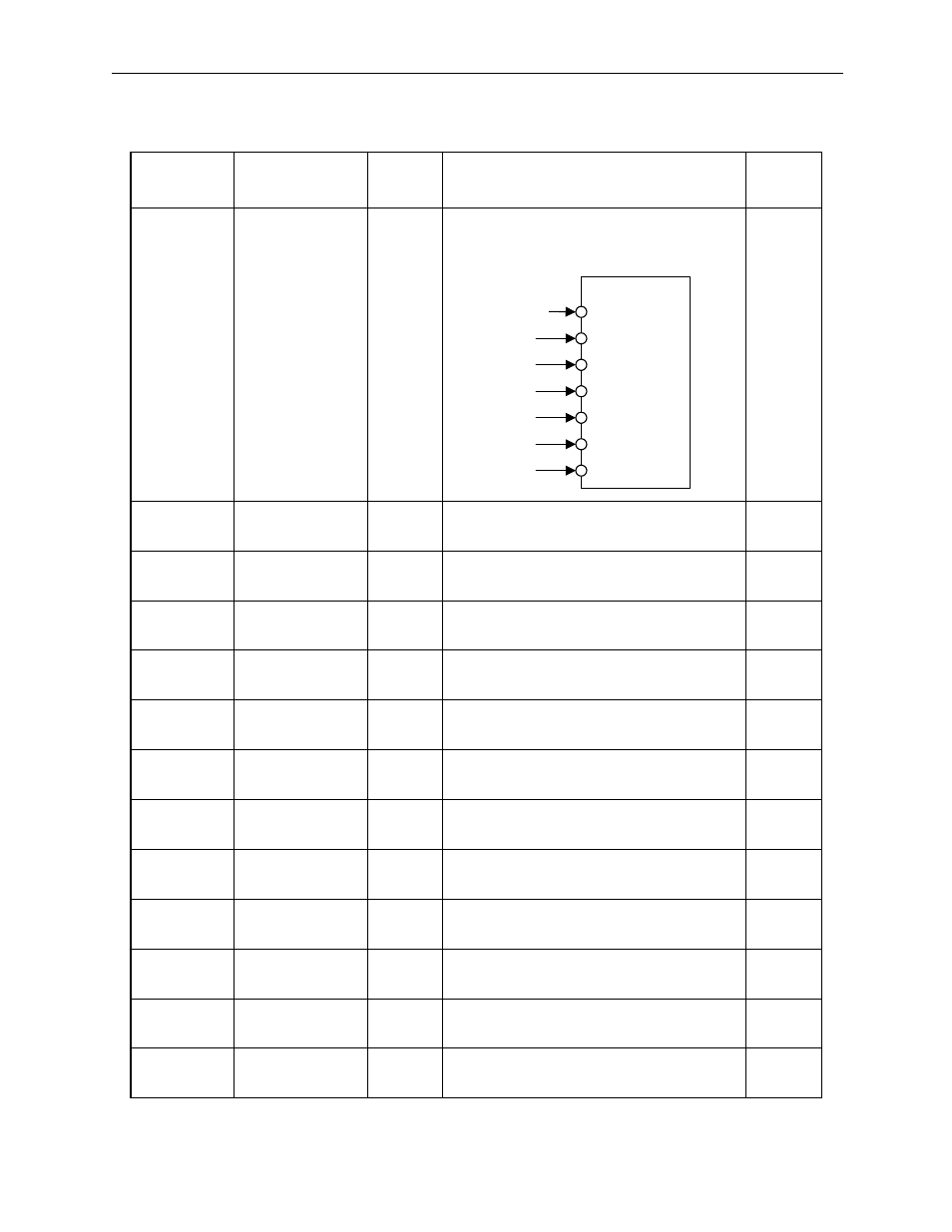
Set the following sequence input signal cir-
cuit assignments when using in connection
with the MP940.
—
Pn50A.0
—
1
The sequence input signal can be set as
desired.
0
Pn50A.167
/S-ON
Signal Mapping
8
The signal is fixed at “Disabled”
/S-ON uses signals on the global memory
0
Pn50A.2
/P-CON
Signal Mapping
8
The signal is fixed at “Disabled”
/P-ON uses signals on the global memory
1
Pn50A.3
/P-OT
Signal Mapping
2
Inputs the P-OT signal from the SI2 (CN1-
42) input terminal.
2
Pn50B.0
N-OT
Signal Mapping
3
Inputs the P-OT signal from the SI3 (CN1-
43) input terminal.
3
Pn50B.1
/ALM-RST
Signal Mapping
8
Signal is fixed at “disabled”
4
Pn50B.2
/P-CL
Signal Mapping
8
Signal is fixed at “disabled”
5
Pn50B.3
N-CL
Signal Mapping
8
Signal is fixed at “disabled”
6
Pn511.0
/DEC
Signal Mapping
1
Inputs the /DEC signal from the SI1 (CN1-
41) Input terminal.
8
Pn511.1
/EXT 1
Signal Mapping
4
Inputs the /EXT 1 signal from the SI4
(CN1-44) input terminal.
8
Pn511.2
/EXT 2
Signal Mapping
5
Inputs the /EXT 2 signal from the SI5
(CN1-45) input terminal.
8
Pn511.3
/EXT 3
Signal Mapping
6
Inputs the /EXT 3 signal from the SI6
(CN1-46) input terminal.
8
Disabled
/DEC
/P-OT
/N-OT
/EXT1
/EXT2
/EXT3
40 SI0
41 SI1
42 SI2
43 SI3
44 SI4
45 SI5
46 SI6
CN1