Yaskawa MP940 Reference Manual User Manual
Page 146
Handling Each Part
MotionSuite™ MP940 Machine Controller Reference Manual
5-4
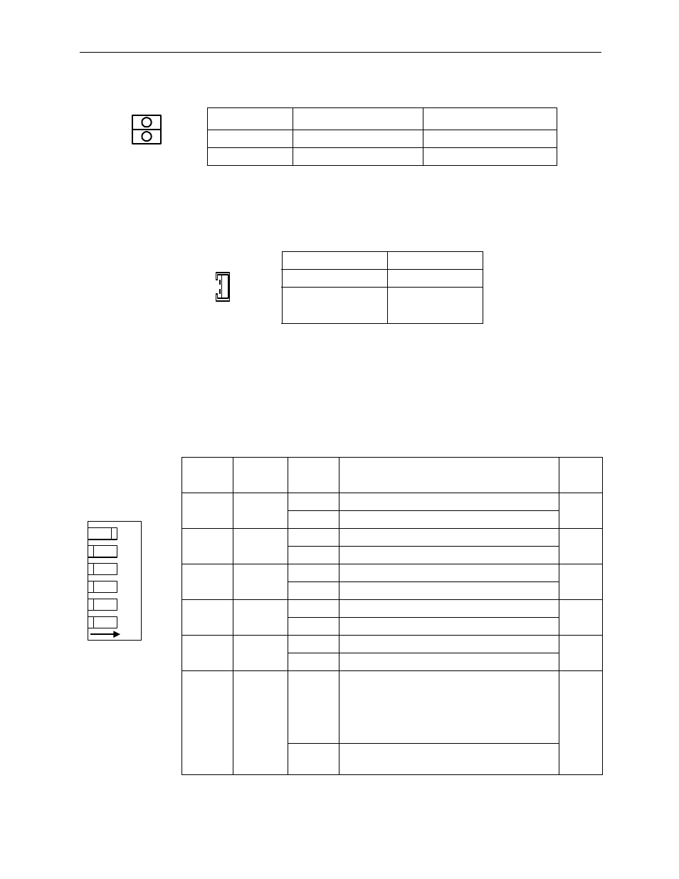
LED 2 shows the Mechatrolink status.
The battery connector connects the program memory backup battery.
• Connector Model:DF3-2P-2DS (HIROSE)
• Battery :ER6VLY+DF3.CONNECTOR
DIP Switches
There are six DIP switches, numbered 1 ~ 6 as shown in the figure below.
Each switch is ON when flipped to the right. Each switch setting is enabled
at the next timing. The function of each switch is shown in the following
table.
Name
Display Light Color
Meaning when Lit
RX
Green
Data reception
TX
Green
Data transmission
Terminal Name
Function
BAT IN
Battery Input
GND
Ground
Number
Name
Setting
Operation at Setting
Default
Setting
6
RUN
ON
User Program Run
ON
OFF
User Program Stop
5
INITIAL
ON
When SW4 is ON: Clear Memory
OFF
OFF
When SW4 is ON: Terminal mode
4
TEST
ON
Terminal Mode/Initialization Mode
OFF
OFF
Online
3
FLASH
ON
Program copy from FLASH to RAM
OFF
OFF
No program copy from FLASH to RAM
2
P.P
Default
ON
Default Port 1 only
OFF
OFF
Serial port setting
1
COPY
ON
M Register Copy when SW3 is ON
Turn the power ON when only SW1 is ON.
SGDH servo parameter in the controller is
transferred to SGDH .
→
to replace
SGDH.
OFF
OFF
No M Register Copy when SW3 is ON.
M Register has a battery backup.
TX
RX
BAT
6
5
4
3
2
1
NO
RUN
INIT
TEST
FLASH
P.P
COPY
ON
OFF