Configuring remote at-cm line cards from the menus – Allied Telesis AT-S99 User Manual
Page 174
Chapter 6: Configuring AT-CM Line Cards with Remote Peer Management
174
Configuring Remote AT-CM Line Cards from the Menus
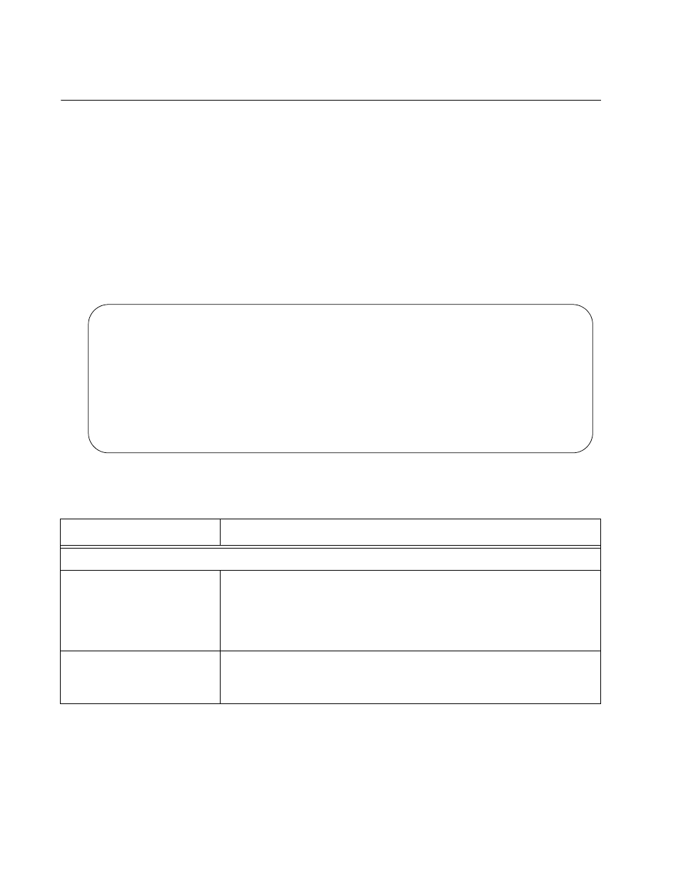
To configure remote AT-CM Line Cards from the menus:
1. From the Main Menu, select Remote Module Status and
Configuration to display the Remote Module Status and
Configuration Menu, shown in Figure 76. The menu shows the status
of the remote peer connections between the fiber optic ports on the
local AT-CM Line Cards in the managed chassis and their remote line
card counterparts. It also displays the states of the fiber optic ports and
twisted pair ports on the remote line cards. The columns are described
in Table 20. (This menu does not display any information for AT-CV
Line Cards.)
Figure 76. Remote Module Status and Configuration Menu
Remote Module Status and Configuration
Converteon
============ LOCAL MODULE ============ ======== REMOTE MODULE ======== ===== FIBER PORT ===== ======= COPPER PORT =======
Mod_Name
CardTypeVer
ST
OV
IPC
VER
Mod_Name
CardTypeVer VER
OV SP
FC IngRL EgrRL OAM ST SP
FC IngRL EgrRL AN
1
AT-CV5M02
*
A
502
V300
2 Reg11
AT-CM202-v2
*
Y
00*
V300 Reg11_r
AT-CM202-v2 V300 Y
100 Y
0
0
*** o
100 Y
0
0
Y
3 Reg20
AT-CM202-v2
*
Y
*0*
V300 Reg20_r
AT-CM202-v2 V300 Y
100 Y
0
0
*** o
100 Y
0
0
Y
4 Reg21
AT-CM202-v2
*
Y
*0*
V300 Reg21_r
AT-CM202-v2 V300 Y
100 Y
0
0
*** o
100 Y
0
0
Y
5 Area2a
AT-CM202-v2
*
Y
*0*
V300 Area2a
AT-CM202-v2 V300 Y
100 Y
0
0
*** o
100 Y
0
0
Y
6 Area2b
AT-CM202-v2
*
Y
*0*
V300 area2b
AT-CM202-v2 V300 Y
100 Y
0
0
*** o
100 Y
0
0
Y
7 Reg12
AT-CM202-v2
*
Y
*0*
V300 Reg12_r
AT-CM202-v2 V300 Y
100 Y
0
0
*** o
100 Y
0
0
Y
8
AT-CV102
-
-
---
---- --------
----------
---- -
--- -
-
-
--- -
--- -
-
-
-
9
AT-CV102
-
-
---
---- --------
----------
---- -
--- -
-
-
--- -
--- -
-
-
-
10
AT-CV102
-
-
---
---- --------
----------
---- -
--- -
-
-
--- -
--- -
-
-
-
11
AT-CV102
-
-
---
---- --------
----------
---- -
--- -
-
-
--- -
--- -
-
-
-
12
AT-CV102
-
-
---
---- --------
----------
---- -
--- -
-
-
--- -
--- -
-
-
-
Table 20. Remote Module Status and Configuration Menu
Column
Description
LOCAL MODULE
Mod_Name
This column lists the chassis slot numbers and the names of the
local AT-CM Line Cards in the chassis that contains the
management card. For instructions on how to assign names to local
line cards, refer to “Assigning Names to AT-CM Line Cards” on
page 149.
CardTypeVer
This column displays the model names of the management cards
and the line cards in the local chassis. The model names of newer
versions of the AT-CM Line Cards have suffixes, like “-v2.”