Rockwell Automation 7000L PowerFlex Medium Voltage AC Drive (C-Frame) - ForGe Control User Manual
Page 84
84
Rockwell Automation Publication 7000L-UM301D-EN-P - June 2014
Chapter 2
Drive Installation
To avoid radiated and/or conducted noise, power and signal lines should be run
separately with a minimum distance between them of at least 75 mm (3 inches).
If they have to overlap somewhere in the system, then the power lines should be
run at 90° to the signal lines. Signal lines should also use twisted pair shielded
cable and run in separate conduit that should be grounded to the building
ground.
Encoder wires and shields should maintain continuity throughout, from the
encoder to the drive. Avoid the use of a terminal block in a junction box. This has
the potential of creating radiated noise and ground loops.
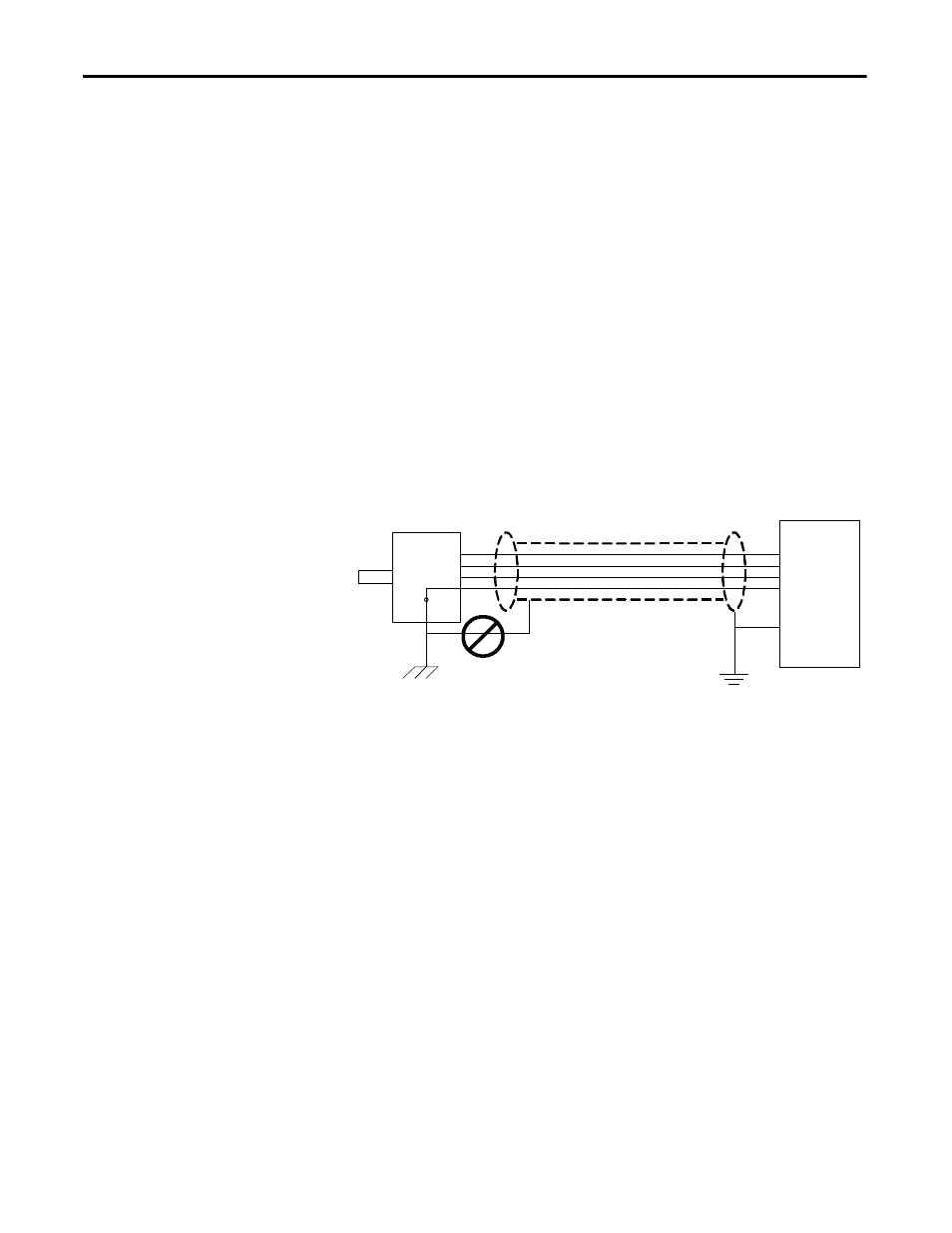
The encoder case must be grounded to the building ground to insure proper and
reliable operation. Most encoders have provision for a case ground connection
through the connector/cable pair if a ground connection cannot be made
through the mounting bracket/machine ground. DO NOT ground the encoder
case through both the machine and cable wiring. Use low capacitance wires
(≤40pf/ft) with 100% shield coverage for long cable runs and connect the shield
only at the drive end.
Figure 67 - Detail Power Terminal Dimensions
For more protection against electrical noise, specify an encoder with
complementary outputs and connect with twisted pair cable. With this type of
cabling, the induced currents will self-cancel.
As a final precaution, ground the shield together with all other parts of the system
that require grounding to a single point ground. This will reduce varying ground
potentials caused by high current fluxes created by motors, remote control
switches and magnetic fields.
Signal Distortion
The primary cause of signal distortion is cable length, more specifically cable
capacitance. Generally speaking the longer the cable length the more there is a
chance of signal distortion at the receiving end. The receiving end responds to
either a logical ‘0’ or a logical ‘1’. Anywhere in between is undefined and the
transition through this region should be < 1.0us. If the leading edge of the
waveform is distorted it causes the transition time through this region to increase.
At some point, the receiver may become unstable and either gain or lose encoder
counts.
Wrong Shield
Connection
Encoder
Drive