Direct-to-drive” technology – Rockwell Automation 7000L PowerFlex Medium Voltage AC Drive (C-Frame) - ForGe Control User Manual
Page 19
Rockwell Automation Publication 7000L-UM301D-EN-P - June 2014
19
Overview of Drive
Chapter 1
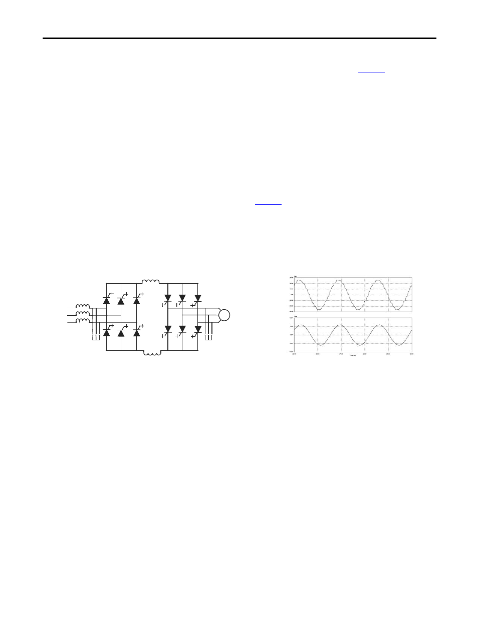
The AFE rectifier requires a switching pattern that complies with similar rules as
the inverter. The pattern, used for the example shown in
, is a 42-pulse
selective harmonic elimination (SHE) pattern, which eliminates the 5th, 7th and
11th harmonics. The integral input capacitors are designed to reduce the current
harmonics of the higher order. The filter transfer function technique is used to
place the filter break frequency in a region where no harmonics are present. This
prevents the excitation of system harmonic frequencies. Other factors that are
considered when designing the filter are the input power factor and the
requirement on Total Harmonic Distortion (THD) of input current and voltage
waveforms.
The AFE rectifier is ideal when a distribution transformer is required to step
down the distribution voltage to match the VFD and motor voltage. The rectifier
input current, the rectifier terminal voltage and the line current and voltage
waveforms are shown in
. The line current THD is approximately 4.5%,
while line-to-line voltage THD is approximately 1.5%. (THD of line voltage is a
function of system impedance.) Input power factor with the AFE rectifier is
equal to or greater than 0.98 for the typical speed and load range when applied to
variable torque loads.
Figure 3 - Active rectifier (PWM) and its input current/voltage waveforms
“Direct-to-Drive” Technology
The PowerFlex 7000L with “Direct-to-Drive” technology allows you to:
•
connect supply power directly to the drive without an Isolation
Transformer
•
connect a new or existing motor directly to the drive without extra motor
filtering.
Most Medium Voltage Drive Manufacturers use multi-winding isolation
transformers to mitigate unwanted harmonics by phase shifting the transformer
secondary windings. Depending on the topology, the transformer can have up to
15 sets of secondary windings. The disadvantages to this method are the high
degree of drive and transformer complexity, a very high component count and
many interconnecting cables and connection points. This leads to much higher
maintenance requirements and lower reliability.
Line
current
Line-to-line
voltage at PCC