Hall effect sensor replacement – Rockwell Automation 7000L PowerFlex Medium Voltage AC Drive (C-Frame) - ForGe Control User Manual
Page 281
Rockwell Automation Publication 7000L-UM301D-EN-P - June 2014
281
Component Definition and Maintenance
Chapter 5
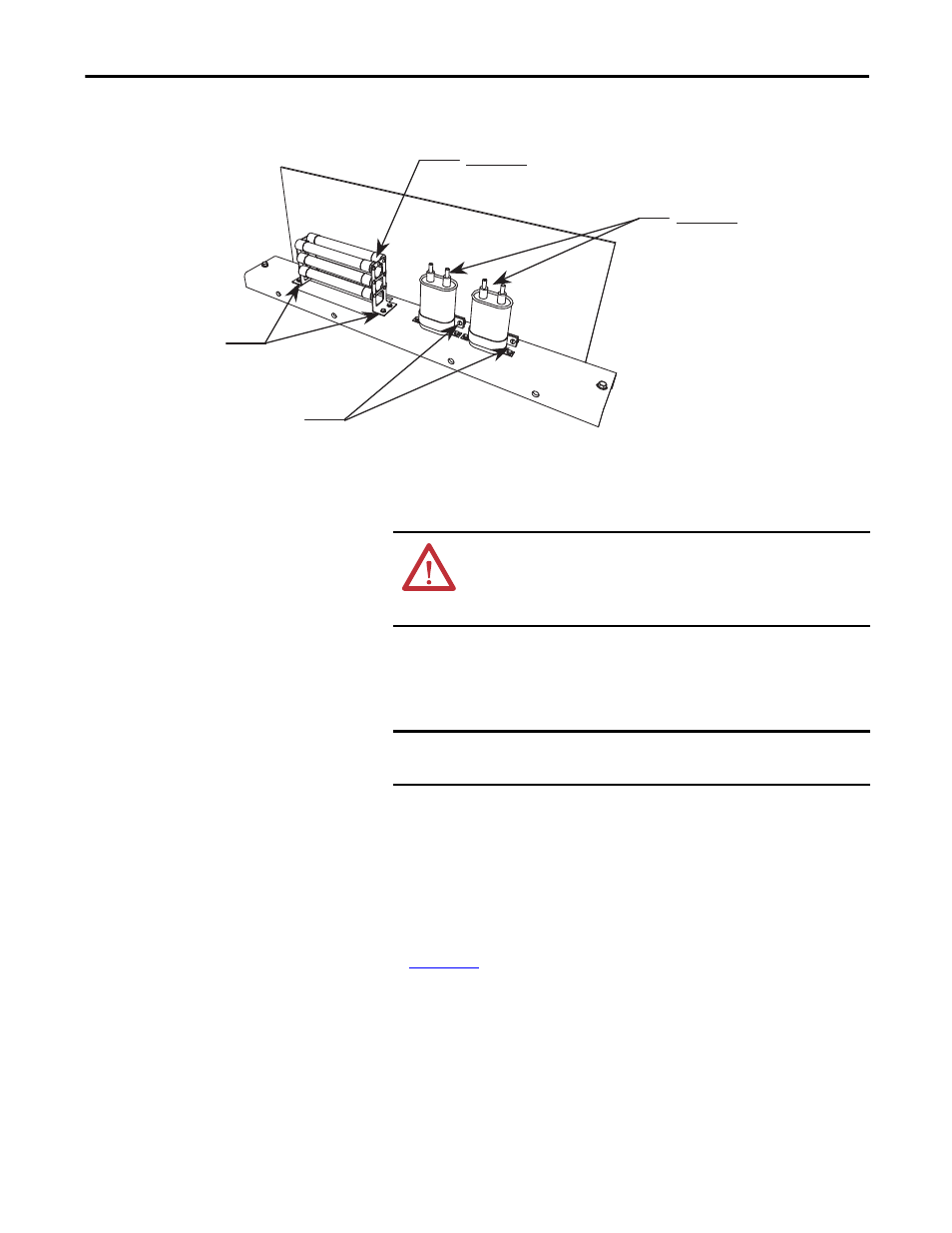
Figure 232 - Ground Filter Capacitor/Resistor
Hall Effect Sensor
Replacement
1.
Ensure there is no power to the equipment.
2.
Note the location of all wires and the orientation of the Hall Effect sensor.
For quick reference, look for the white arrow when checking the
orientation of the Hall Effect sensor.
3.
The round bus bar must be removed. Remove the M10 hardware and slide
the bar out.
4.
Remove the screws from the three terminals to allow removal of the ring
lugs.
5.
Remove the four screws on the base of the Hall Effect sensor.
6.
Replace the Hall Effect sensor. Note the arrow must be oriented as shown
in
.
7.
Slide the bus bar back into place and secure with the M10 hardware.
8.
Fasten the ring lugs on the wires back into place in the correct position. Do
not overtighten or you will break the threaded stud.
Important!
Torque on Resistor Bank Assembly
1,2 Nm (11.0 lb-in) maximum
Loosen screws to release capacitors
Remove screws for
replacing resistor bank.
Important!
Torque on capacitor terminals
3,4 Nm (30 lb-in) maximum
ATTENTION: To prevent electrical shock, ensure the main power has
been disconnected before working on the Hall Effect sensor. Verify that
all circuits are voltage free using a hot stick or appropriate voltage-
measuring device. Failure to do so may result in injury or death.
IMPORTANT
The Hall Effect sensor and wires must be in the proper orientation.
Note the position before disassembly.