Sgct testing – Rockwell Automation 7000L PowerFlex Medium Voltage AC Drive (C-Frame) - ForGe Control User Manual
Page 197
Rockwell Automation Publication 7000L-UM301D-EN-P - June 2014
197
Commissioning
Chapter 4
•
Inverter or AFE Rectifier Bridge
–
Anode-to-Cathode Resistance Test (Sharing Resistor and SGCT)
–
Snubber Resistance Test (Snubber Resistor)
–
Snubber Capacitance Test (Snubber Capacitor)
•
SCR Rectifier Bridge
–
Anode-to-Cathode Resistance Test (Sharing Resistor and SCR)
–
Gate-to-Cathode Resistance Test (SCR)
–
Snubber Resistance Test (Snubber Resistor)
–
Snubber Capacitance Test (Snubber Capacitor)
SGCT Testing
The following instructions outline the procedure to be taken when verifying
SGCT semiconductors and all snubber components. Expected SGCT Snubber
Circuit Resistance and Capacitance values are listed in
Table 6 - SGCT Snubber Circuit Resistance and Capacitance Values
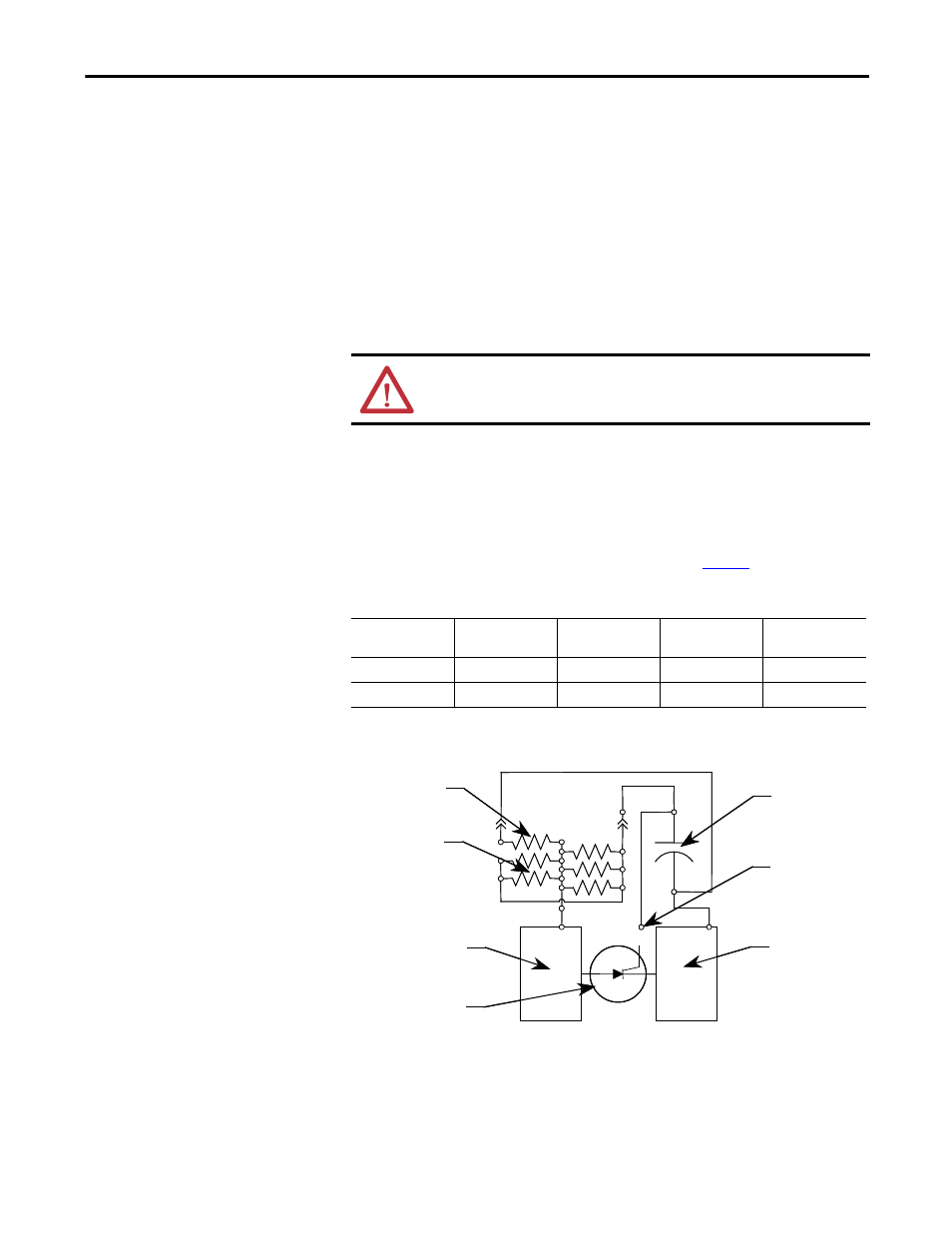
Figure 181 - SGCT Snubber Circuit Connections
ATTENTION: Before attempting any work, verify that the system has been
locked out and tested to have no potential.
Drive Rating
Sharing
Resistance
Snubbe
Resistance
Snubber
Capacitance
Inverter
3300 to 6600 V
80 kΩ
7.5 Ω
0.5 μf
AFE Rectifier
3300 to 6600 V
80 kΩ
6.0 Ω
0.5 μf
Sharing Resistor
Snubber Resistors
Qty. 4 or 5
Anode Chill Block
SGCT
Cathode Chill Block
Test Point
Snubber Capacitor
Sharing Resistor
Snubber Resistors
Qty. 4 or 5
Anode Chill Block
SGCT
Cathode Chill Block
Test Point
Snubber Capacitor