Rockwell Automation 7000L PowerFlex Medium Voltage AC Drive (C-Frame) - ForGe Control User Manual
Page 223
Rockwell Automation Publication 7000L-UM301D-EN-P - June 2014
223
Commissioning
Chapter 4
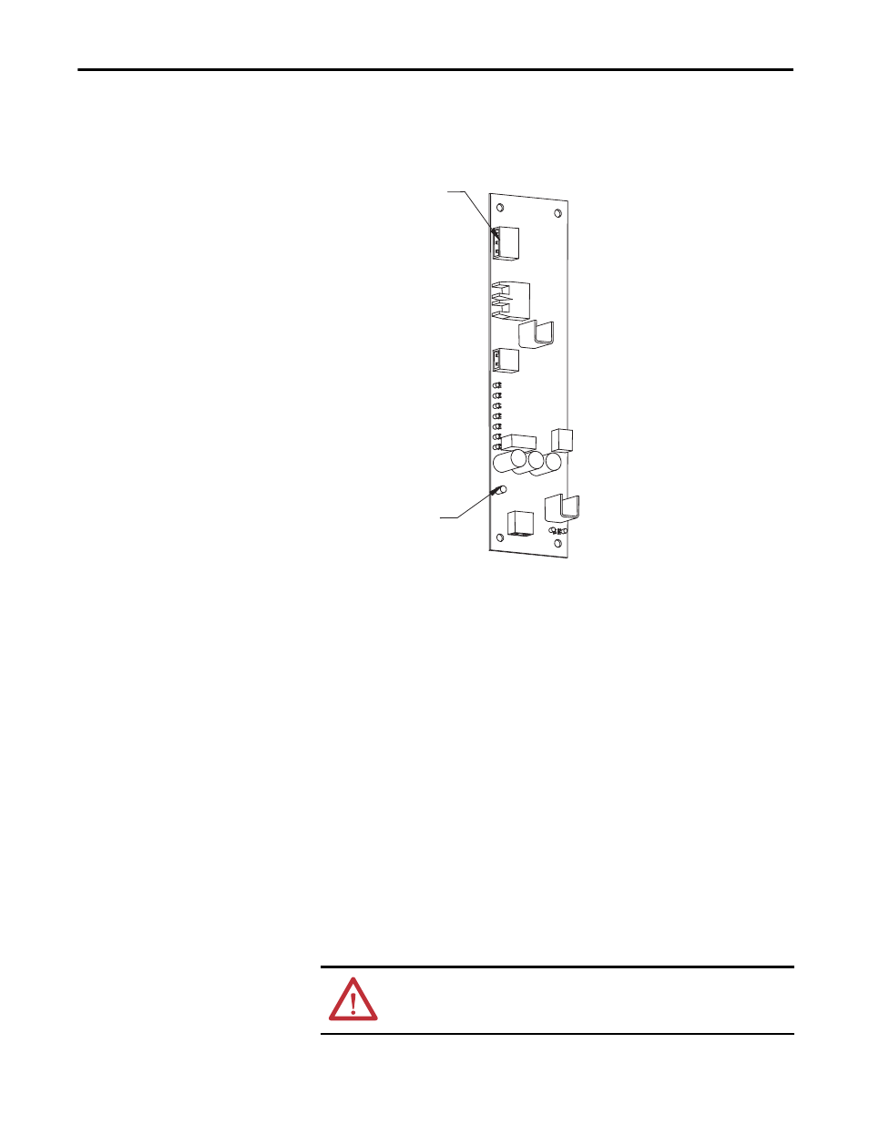
Power Terminal). The number of eighteen 3-pin connectors used will depend on
the voltage and configuration of the drive rectifier section.
Figure 202 - Self-Powered Gate Driver Board Test Power Terminal
Put the drive in Gating Test Mode and the rectifier will automatically go into Test
Pattern gating mode.
LED 1 – Gate Pulse (Yellow) should light up and pulsate at the frequency that
the device is firing. All the other LEDs will light up as the firmware sends a gating
signal to every SCR.
There is also a Gating Test that fires the individual devices one at a time, in what
is described as a Z-pattern. Basically, for each section, the Top Left device will
turn on for 2 seconds, then turn off. The next device to the right will turn on for
2 seconds, and the pattern will continue. When you reach the end of the first
stack of devices, the right device in the middle stack down will fire and the
pattern continues right to left until the end of the middle stack is reached. Then
the left device in the bottom stack will fire and the pattern will continue to the
last device, where it will then return to the top. This is a test to show that the
correct fiber optic cables are connected to the corresponding devices.
During commissioning, it is not necessary to use an oscilloscope for SCR firing
tests, although it will be required if SCR firing problems occur.
ATTENTION: Ensure that the test cable is removed from the drive and that it is
taken out of Test Mode prior to applying Medium Voltage. Failure to do so may
result in personal injury or equipment damage.
Test power connection
LED