Joining shipping splits – Rockwell Automation 7000L PowerFlex Medium Voltage AC Drive (C-Frame) - ForGe Control User Manual
Page 38
38
Rockwell Automation Publication 7000L-UM301D-EN-P - June 2014
Chapter 2
Drive Installation
The location of the anchor points is provided with the dimension drawing of the
drive.
Install and tighten the anchor bolts. (M12 or 1/2" hardware required).
Engineered bolt systems are required for seismic requirements. Consult factory.
Remove the top lifting angles, retain the hardware.
Install the hardware from the lifting angles in the tapped holes at the top of drive;
this prevents leakage of cooling air as well as keeping dust out of the equipment.
Joining Shipping Splits
The Drive may have been shipped in two or more shipping sections which are to
be connected at installation. It is essential that the surfaces are level. Arrange the
sections per the information provided in the dimension drawings and move the
sections together. Ground bus, power and control connections are to be made per
the electrical diagrams provided. Side sheets of the enclosures are to be joined
with thread forming screws using the available holes.
Liquid-cooled Drives may require joining of the coolant pipes. Some enclosure
ratings may require the addition of silicone sealant where cabinets join together
to prevent the possible ingress of dripping water.
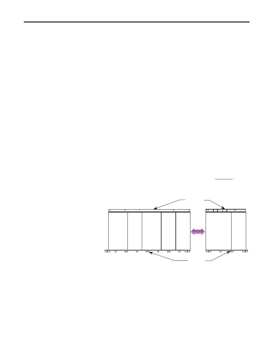
For Direct-to-Drive liquid-cooled 6600V Drives (430A, 495A and 575A rated
current) the Drive will be shipped in two sections as shown in
.
Figure 15 - Typical Split Drive
The 1st section consists of 5 cabinets.
The 2nd section consists of 2 cabinets.
Final placement requires that the 1st and 2nd sections are joined at final
installation site.
LR
CAB
1
CABLE
CAB
2
CONV
CAB
3
CAP
CAB
4
CAP
CAB
5
DC LINK
CHOKE
CAB
6
PUMP
CAB
7
Lifting Angles
Wood Skid
1st SECTION
2nd SECTION