Snubber resistors, Figure 254 – Rockwell Automation 7000L PowerFlex Medium Voltage AC Drive (C-Frame) - ForGe Control User Manual
Page 306
306
Rockwell Automation Publication 7000L-UM301D-EN-P - June 2014
Chapter 5
Component Definition and Maintenance
5.
After the PowerCage is securely fastened to the backplane refer to the
appropriate sections to replace all other components.
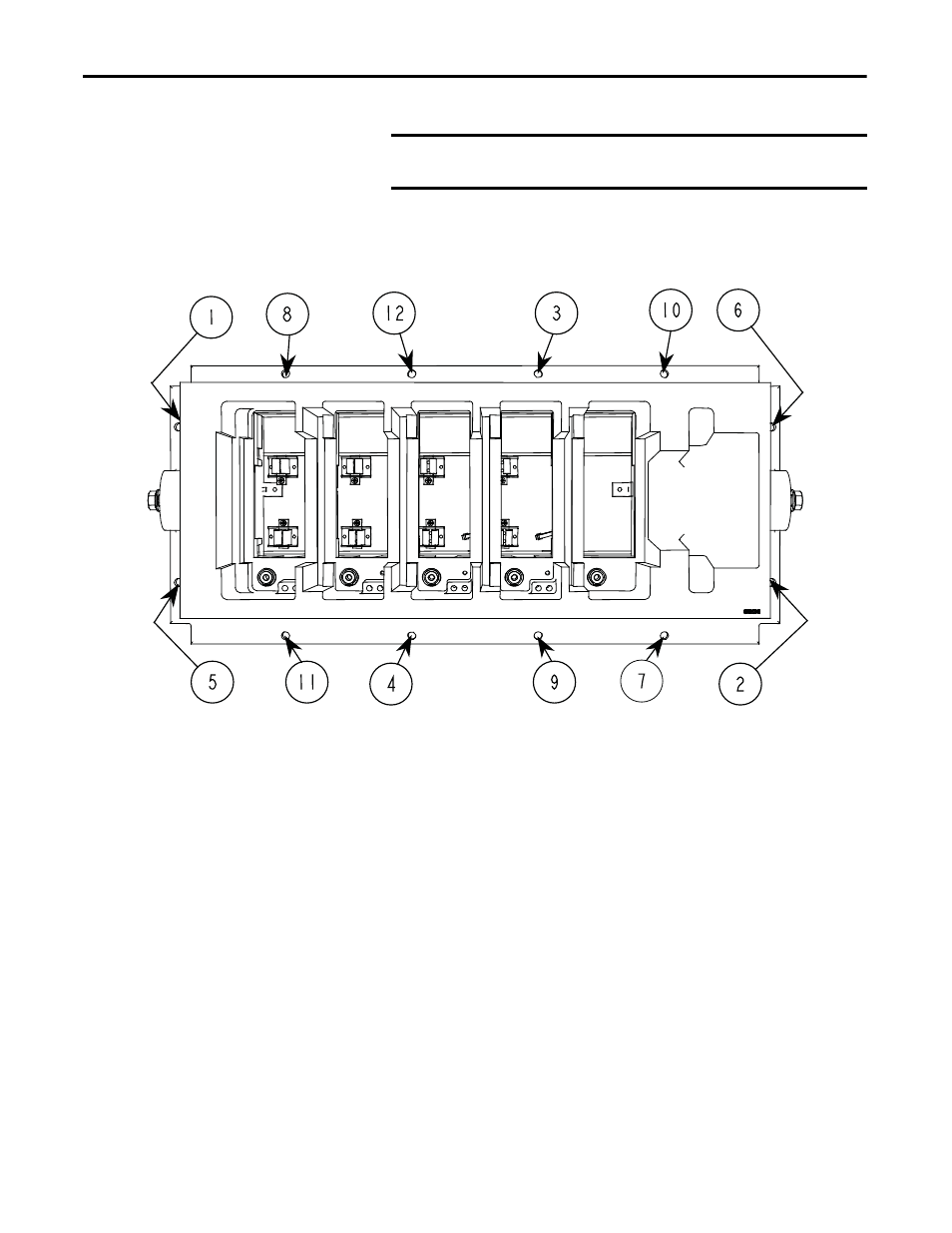
Figure 254 - Typical Torque Sequence
Snubber Resistors
A test point is provided inside the PowerCage to measure the resistance of the
snubber resistor and capacitance of the snubber capacitor. The test point is the
electrical connection between the snubber resistor and snubber capacitor. The
procedure is to place one probe of the multi-meter on the test point and the other
probe on the appropriate chill block to determine the value of the resistor or
capacitor.
Snubber resistors are connected in series with the snubber capacitors. Together
they form a simple RC snubber that is connected across each semiconductor
(SCR or SGCT). The purpose of the snubber circuit is to reduce the dv/dt stress
on the semiconductors and to reduce the switching losses. The snubber resistors
are connected as sets of thick film resistors. The number of resistors depends on
the type of the semiconductor and the configuration and frame size of the drive.
IMPORTANT
When replacing the PowerCage, always be sure all the PowerCage
components are removed.