Sgct firing test – Rockwell Automation 7000L PowerFlex Medium Voltage AC Drive (C-Frame) - ForGe Control User Manual
Page 224
224
Rockwell Automation Publication 7000L-UM301D-EN-P - June 2014
Chapter 4
Commissioning
SGCT Firing Test
Unlike the SCR Self-powered gate Driver Board, the SGCT has an integrated
firing circuit mounted on the device. The power for this circuit is derived from
the SGCT Power Supplies (IGDPS), and preliminary observations are possible
by monitoring the healthy lights on the firing circuit without putting the drive
into gating test mode. There are 4 LEDs on the firing card. The following
diagram illustrates the location of the LEDs:
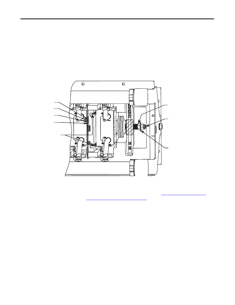
Figure 203 - SGCT Healthy LEDs
While the drive is sitting idle, without gating LEDs 4 (Green), 3 (Green), and 1
(RED) should be illuminated while LED 2 (Yellow) is off. If any other
combinations of LEDs are illuminated, refer to
Maintenance on page 265 (Chapter 5)
, for instructions on how to troubleshoot
the SGCT firing cards.
Put the drive in Gating Test Mode and the inverter will automatically go into the
Test Pattern gating mode.
Monitor the SGCT LEDs and ensure that LEDs 4 (Green) and 3 (Green) remain
illuminated, while LEDs 1 (Red) and 2 (Yellow) toggle on an off alternately at
the frequency that the converter is operating at.
There is also a Gating Test that fires the individual devices one at a time, in what
is described as a Z-pattern. Basically, for each section, the Top Left device will
turn on for 2 seconds, then turn off. The next device to the right will turn on for
2 seconds, and the pattern will continue. When you reach the end of the first
stack of devices, the right device in the middle stack down will fire and the
pattern continues right to left until the end of the middle stack is reached. Then
Clamp Adjusting Nut
Indicating Washer
Do Not Adjust Calibration Nut
SGCT
Retaining
Screws
LED 4
LED 3
LED 2
LED 1
Clamp Adjusting Nut
Indicating Washer
Do Not Adjust Calibration Nut
SGCT
Retaining
Screws
LED 4
LED 3
LED 2
LED 1