Voltage-sensing assembly, Voltage-sensing circuit board assembly replacement – Rockwell Automation 7000L PowerFlex Medium Voltage AC Drive (C-Frame) - ForGe Control User Manual
Page 269
Rockwell Automation Publication 7000L-UM301D-EN-P - June 2014
269
Component Definition and Maintenance
Chapter 5
Voltage-Sensing Assembly
The voltage-sensing assembly consists of the voltage sensing board and the
mounting plate. The voltage sensing board has six independent channels which
convert voltages up to 10800V (7.2kV x 1.5 pu) down to low voltage levels which
can be used by the PowerFlex 7000 control logic (i.e. Signal Conditioning Board
- SCB). Two of these assemblies can be linked together where one assembly acts
as the master assembly, and the second assembly acts as the slave assembly. In this
manner, up to twelve independent voltage channels can be measured. When two
assemblies are linked together, the master assembly is used to send the twelve
voltage signals to the SCB board. For drives that require the synchronous transfer
option, one additional module is used. This assembly uses a separate connector to
output the transfer voltages directly to the SCB board.
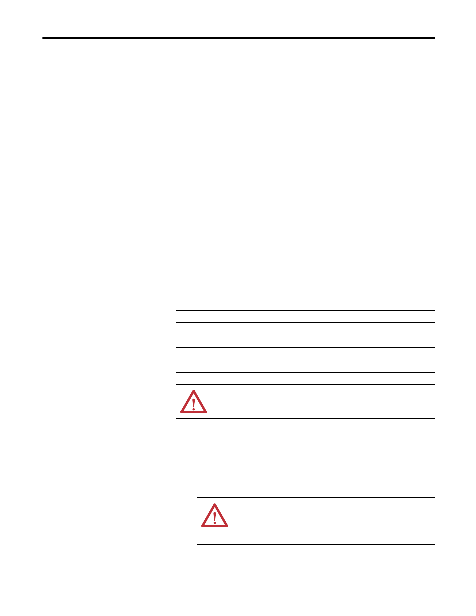
Below is a table of the input voltage ranges for each of the input terminals on the
voltage-sensing board. There are four separate inputs taps for each of the six
independent channels. This assembly has been designed to operate at a nominal
input voltage of up to 7200V with a continuous 40% overvoltage. The output
voltages are scaled to provide close to 10V peak for a 140% input voltage at the
high end of each of the voltage ranges.
Each of the channels has only four taps, thus they must be used to provide a range
of input voltages and software will be used to provide a given amount of gain so
that 140% will correspond to the maximum numerical value of the analogue to
digital converter.
Table 20 - Nominal Input Voltage Ranges
Voltage-Sensing Circuit
Board Assembly
Replacement
The number of sensing boards is dependent upon the drive rectifier
configuration.
1.
Ensure there is no power to the equipment.
2.
Mark the position of the ribbon cables and wires.
Tap
Voltage Range
D
800 - 1449V
C
1450 - 2499V
B
2500 - 4799V
A
4800 - 7200V
ATTENTION: Grounds must be reconnected on the voltage sensing boards.
Failure to do so may result in injury, death or damage to equipment.
ATTENTION: To prevent electrical shock, ensure the main power has
been disconnected before working on the sensing board. Verify that all
circuits are voltage free using a hot stick or appropriate high voltage-
measuring device. Failure to do so may result in injury or death.