Rockwell Automation 7000L PowerFlex Medium Voltage AC Drive (C-Frame) - ForGe Control User Manual
Page 241
Rockwell Automation Publication 7000L-UM301D-EN-P - June 2014
241
Commissioning
Chapter 4
10.
Stop the drive. Set parameters
Operating Mode to Normal and Idc
Command Test to zero.
T DC Link (P#115) Manual Tuning
An appropriate value for the
T DC Link parameter can be determined from the
current regulator step response while operating in
DC Current test mode. The
following procedure should be followed:
1.
Be sure that all the parameters in the
Drive Hardware and Motor Ratings
groups have been set to the correct values. Otherwise, the calculated value
of parameter
T DC Link in Current Control will not be correct.
2.
Set parameter
Operating Mode in the Feature Select to DC Current to enter
dc current test mode.
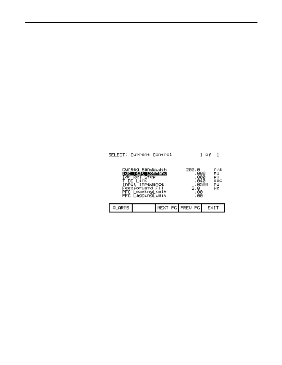
Figure 208 - Current Control Parameter Screen
3.
Set parameter
Idc Test Command in Current Control to 0.225 pu for AFE
rectifier drives and 0.400 pu for SCR drives.
4.
Set parameter
CurReg Bandwidth in Current Control to 100 rad/sec. A
lower than the normal bandwidth makes the step response easier to
measure.
5.
Set parameter
T DC Link in Current Control to 0.020 sec, which is at the
low end of the normal range of values and should produce an under-
damped response.
6.
Assign parameters
Idc Reference and Idc Feedback in the Current Control
group to 2 DPM test points e.g. RTP1 and RTP2. This can be done
similarly to the way that the meter assignments were described earlier in
the chapter. Then they can be displayed on the oscilloscope.
7.
Start the drive. Set parameter
Idc Ref Step in Current Control to 0.075pu
for AFE rectifier drive and 0.200 pu for SCR drives. The dc link current
will step up and down by this amount at regular intervals.
L
in
3 V
in0
V
in1
–
I
dc
----------------------------------
=
for SCR drives