Optic test – Teledyne 6200E - Sulfides Analyzer User Manual
Page 95
Model 6200E Instruction Manual
Operating Instructions
M6200E Rev: A1
95
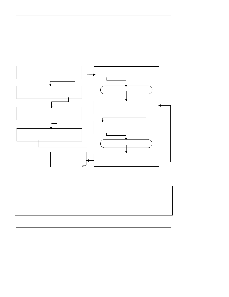
6.9.5. Optic Test
The optic test function tests the response of the PMT sensor by turning on an LED located in the
cooling block of the PMT (Fig. 10-15). The analyzer uses the light emitted from the LED to test its
photo-electronic subsystem, including the PMT and the current to voltage converter on the pre-
amplifier board. To make sure that the analyzer measures only the light coming from the LED, the
analyzer should be supplied with zero air. The optic test should produce a PMT signal of about
2000±1000 mV. To activate the electrical test press the following key sequence.
SAMPLE RANGE = 500.0 PPB
H2S
=XXX.X
< TST TST > CAL
SETUP
SAMPLE
ENTER SETUP PASS : 818
8 1 8
ENTR
EXIT
SETUP X.X
PRIMARY SETUP MENU
CFG DAS
RNGE
PASS CLK
MORE
EXIT
SETUP X.X
SECONDARY SETUP MENU
COMM VARS
DIAG
EXIT
DIAG
SIGNAL I / O
PREV NEXT
JUMP
ENTR
EXIT
DIAG OPTIC
RANGE = 500.000 PPB SO2=X.XXX
EXIT
Press NEXT until…
DIAG
OPTIC TEST
PREV NEXT
ENTR
EXIT
Press TST until…
DIAG ELEC
PMT = 2751 MV
SO2=X.XXX
EXIT
While the optic test is
activated, PMT should be
2000 mV ± 1000 mV
NOTE
This is a coarse test for functionality and not an accurate calibration tool. The resulting
PMT signal can vary significantly over time and also changes with low-level calibration.