So2 scrubber, Pneumatic sensors, Sample pressure sensor – Teledyne 6200E - Sulfides Analyzer User Manual
Page 216: Scrubber
Theory Of Operation
Model 6200E Instruction Manual
216
M6200E Rev: A1
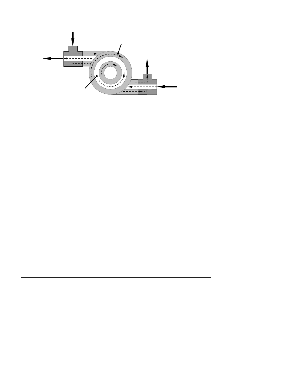
INNER
TUBE
(Ambient Air)
OUTER TUBE
(Clean Air)
SAMPLE AIR
FROM
PARTICULATE FILTER
CLEANED
SAMPLE AIR
TO
SAMPLE
CHAMBER
CLEAN
PURGE AIR
FROM
VACUUM MANIFOLD
USED PURGE AIR
TO
PUMP
AND
EXHAUST PORT
Figure 10-9: M6200E Hydrocarbon Scrubber (Kicker)
In the M6200E some of the cleaned air from the inner tube is returned to be used as the purge
gas in the outer tube (Figure 10-9). This means that when the analyzer is first started, the
concentration gradient between the inner and outer tubes is not very large and the scrubber’s
efficiency is relatively low. When the instrument is turned on after having been off for more than
30 minutes, it takes a certain amount of time for the gradient to become large enough for the
scrubber to adequately remove hydrocarbons from the sample air.
10.3.6. SO
2
Scrubber
In order to ensure that no ambient SO
2
interferes with the analyzer’s H
2
S measurement the
sample gas stream is passed through a chemical scrubber that removes SO
2
from the sample
stream before it is passed though the catalytic converter (see Figure 10-7).
The SO
2
scrubber is a Teflon encased, stand-alone unit containing a room-temperature catalyst
tube mounted in the front right side of the analyzer case (see Figure 3.8) near the instrument’s
on/off switch.
The SO
2
scrubber material is consumed as it removes SO
2
. If the expected concentrations of SO
2
are very high, the lifetime of the scrubber will be short. The expected life of the scrubber is
approximately 1000 ppm-hours. See Section 9.3.3 for information on when and how to replace
the SO
2
scrubber material)
10.3.7. Pneumatic Sensors
The M6200E uses two pneumatic sensors to verify gas streams. These sensors are located on a
printed circuit assembly, called the pneumatic pressure/flow sensor board.
10.3.7.1. Sample Pressure Sensor
An absolute pressure transducer plumbed to the input of the analyzer’s sample chamber is used to
measure the pressure of the sample gas before it enters the chamber. This upstream used to
validate the critical flow condition (2:1 pressure ratio) through the instrument’s critical flow orifice
(Section 10.3.3). Also, if the temperature/pressure compensation (TPC) feature is turned on