Multigas measurement option (option 82), Communication options, Rs232 modem cable (option 60) – Teledyne 6200E - Sulfides Analyzer User Manual
Page 52: Rs-232 multidrop (option 62)
Optional Hardware and Software
Model 6200E Instruction Manual
52
M6200E Rev: A1
5.5.
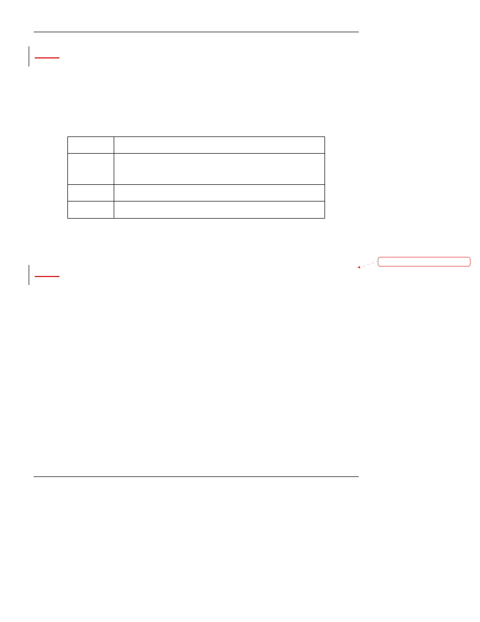
Multigas Measurement Option (option 82)
When installed and operating the multigas measurement option allows the instrument to be
configured so that it can measure either or both H
2
S or SO
2
. A valve directs the sample gas stream
through alternate gas paths that all allowing the analyzer to measure either H
2
S or ambient SO
2.
When the multigas option, is activated, this option the instrument may be used in one of three gas
measurement modes.
Table 5-3: H
2
S – SO
2
Switching Valve Operating States
GAS
MODE
DESCRIPTION
H
2
S
The sample gas stream is stripped of any ambient SO
2
by a special
chemical scrubber, then passed through a catalytic converter that
changes the H
2
S present into SO
2
which is then measured using the
UV Fluorescence method
SO
2
The sample gas stream bypasses the SO
2
Scrubber and catalytic
converter allowing the only ambient SO
2
to be measured.
H
2
S –SO
2
The switching valve alternates the gas stream between the two paths
at regular intervals allowing the instrument to measure both gases.
See Sections 6.8.1 and 10.3.2 for more information
5.6.
Communication Options
5.6.1. RS232 Modem Cable (Option 60)
This option consists of a cable to connect the analyzer’s COM1 port to a computer, a code activated
switch or any other communications device that is equipped with a DB-9 male connector. The cable
is terminated with two DB-9 female connectors, one of which fits the analyzer’s COM1 port.
Some older computers or code activated switches with a DB-25 serial connector will need a
different cable or an appropriate adapter.
5.6.2. RS-232 Multidrop (Option 62)
The multidrop option is used with any of the RS-232 serial ports to enable communications of up to
eight analyzers with the host computer over a chain of RS-232 cables via the instruments COM1
Port. It is subject to the distance limitations of the RS 232 standard.
The option consists of a small printed circuit assembly, which is plugs into to the analyzer’s CPU
card (see Figure 5-4) and is connected to the RS-232 and COM2 DB9 connectors on the
instrument’s back panel via a cable to the motherboard. One option 62 is required for each
analyzer along with one 6’ straight-through, DB9 male Æ DB9 Female cable (P/N WR0000101).
Formatted: Bullets and Numbering