Multidrop rs-232 set up, Multidrop pca – Teledyne 6200E - Sulfides Analyzer User Manual
Page 113
Model 6200E Instruction Manual
Operating Instructions
M6200E Rev: A1
113
Table 6-17: Internet Configuration Keypad Functions
KEY FUNCTION
Moves the cursor one character to the left.
CH>
Moves the cursor one character to the right.
INS
Inserts a character before the cursor location.
DEL
Deletes a character at the cursor location.
[?]
Press this key to cycle through the range of numerals and characters available
for insertion.
0-9, A-Z, space ’ ~ ! © # $ % ^ & * ( ) - _ = +[ ] { } <
>\ | ; : , . / ?
ENTR
Accepts the new setting and returns to the previous menu.
EXIT
Ignores the new setting and returns to the previous menu.
Some keys only appear as needed.
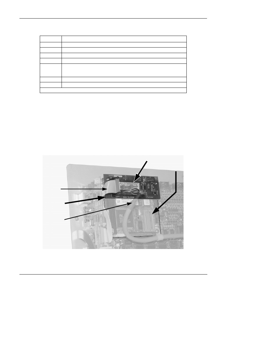
6.10.7. Multidrop RS-232 Set Up
The RS-232 multidrop consists of a printed circuit assembly that plugs onto the CN3, CN4, and CN5
connectors of the CPU card (see Figure 6-9) and the cabling to connect it to the analyzer’s
motherboard. This PCA includes all circuitry required to enable your analyzer for multidrop
operation. It converts the instrument’s COM1 port to multidrop configuration allowing up to eight
analyzers to be connected the same I/O port of the host computer.
Because both of the DB9 connectors on the analyzer’s back panel are needed to construct the
multidrop chain, COM2 is no longer available for separate RS-232 or RS-485 operation, however,
with the addition of an Ethernet Option (option 63, see Sections 5.6.3 and 10.6.6) the COM2 port is
available for communication over a 10BaseT LAN.
Rear Panel
(as seen from inside)
CPU Card
Multidrop
PCA
JP2
Cable to
Ethernet
Card
Cable to
Motherboard
Figure 6-12: Location of JP2 on RS232-Multidrop PCA (option 62)