Ain calibration – Teledyne 6200E - Sulfides Analyzer User Manual
Page 93
Model 6200E Instruction Manual
Operating Instructions
M6200E Rev: A1
93
DIAG AIO
CONC_OUT_2 SPAN: 10000 mV
U100 UP10
UP DOWN DN10
D100
ENTR EXIT
DIAG AIO
AUTO CALIBRATING CONC_OUT_2
DIAG AIO
AIN CALIBRATED:
NO
SET>
EDIT
EXIT
DIAG
ANALOG I / O CONFIGURATION
PREV
NEXT
ENTR
EXIT
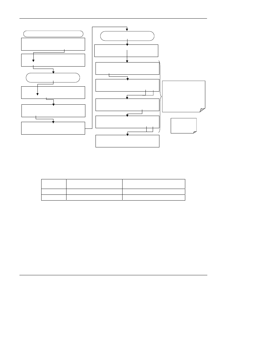
FROM ANALOG I/O CONFIGURATION MENU
DIAG AIO
CONC_OUT_2 RANGE: CURR
SET> EDIT EXIT DIAG AIO CONC_OUT_2 CALIBRATED: NO < SET CAL EXIT DIAG AIO CONC_OUT_2:CURR, NO CAL < SET SET> EDIT EXIT Press SET> to select the analog output channel to be configured:. Increase or decrease the current output by 100, 10 or 1 counts. The resulting change in output voltage is displayed in the upper line. Continue adjustments until the correct current is measured with the current meter. DIAG AIO CONC_OUT_2 ZERO: 27 mV UP DOWN DN10 D100 ENTR EXIT EXIT ignores the new setting, ENTR accepts the new setting. DIAG AIO CONC_OUT_2 CALIBRATED: YES < SET CAL EXIT DIAG AIO CONC_OUT_2 ZERO: 9731 mV UP DOWN DN10 D100 ENTR EXIT DIAG AIO CONC_OUT_2 CURR-Z: 0 mV UP10 UP DOWN DN10 D100 ENTR EXIT The instrument attempt to automatically calibrate the channel … then beep. If a current meter is not available, an alternative method for calibrating the current loop outputs is to connect a 250 Ω ±1% resistor across the current loop output. Using a voltmeter, connected across the resistor, follow the procedure above but adjust the output to the following values: Table 6-13: Current Loop Output Calibration with Resistor FULL SCALE VOLTAGE FOR 2-20 MA (measured across resistor) VOLTAGE FOR 4-20 MA (measured across resistor) 0% 0.5 V 1.0 V 100% 5.0 V 5.0 V 6.9.4.6. AIN Calibration This is the sub-menu to conduct the analog input calibration. This calibration should only be necessary after major repair such as a replacement of CPU, motherboard or power supplies.
U100 UP10
U100 UP10
U100
Activate the ANALOG I/O CONFIGURATION MENU (see Section 6.9.1), then press: