Fault diagnosis with test functions – Teledyne 6200E - Sulfides Analyzer User Manual
Page 242
TROUBLESHOOTING & REPAIR
Model 6200E Instruction Manual
242
M6200E Rev: A1
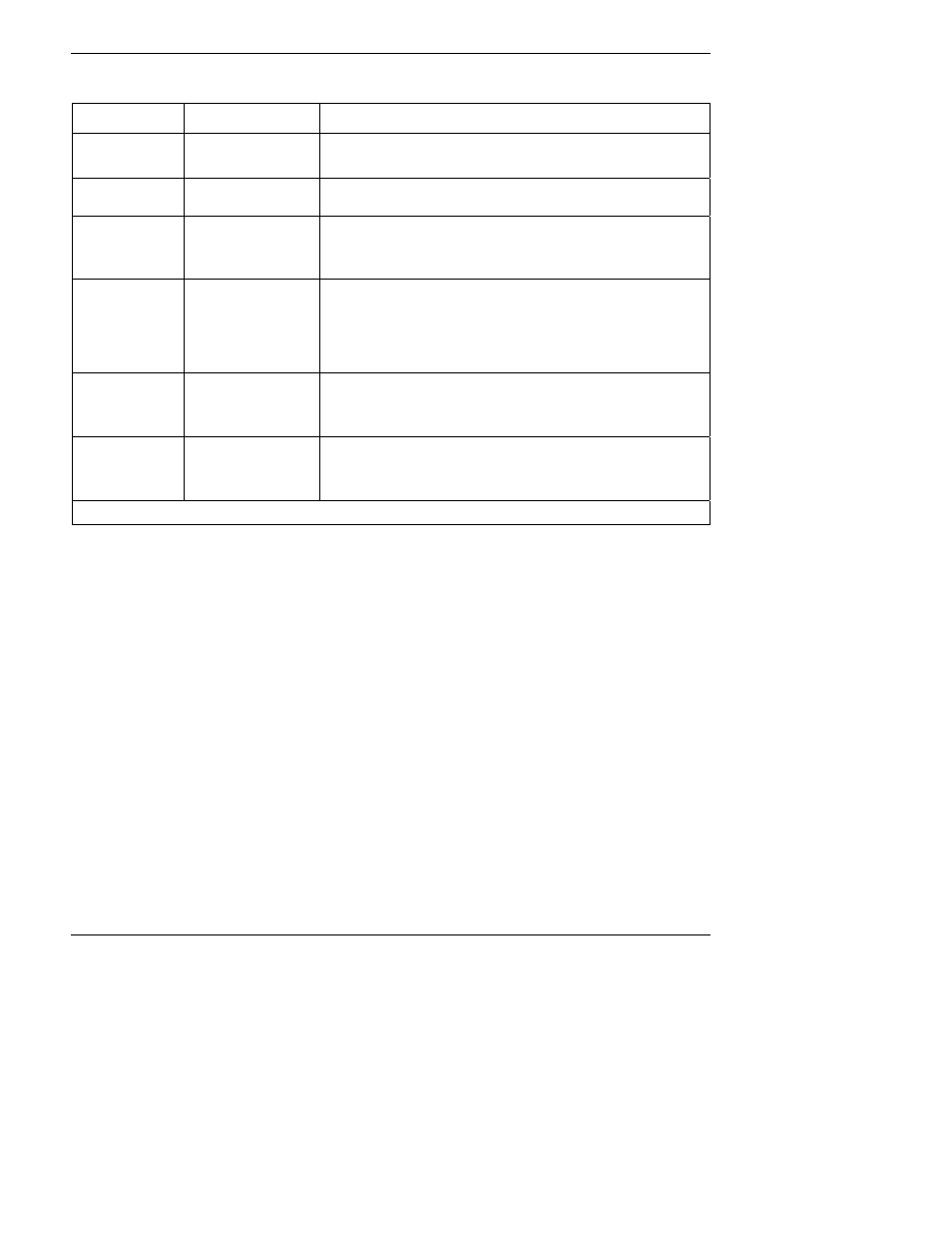
Table 11-1: Warning Messages - Indicated Failures (cont.)
WARNING
MESSAGE
FAULT CONDITION
POSSIBLE CAUSES
REAR BOARD
NOT DET
Mother Board not
detected on power up.
Warning only appears on serial i/o com port(s)
Front panel display will be frozen, blank or will not respond.
Massive failure of mother board.
RELAY BOARD
WARN
The CPU cannot
communicate with the
Relay Board.
I
2
C buss failure
Failed relay board
Loose connectors/wiring
SAMPLE FLOW
WARN
Sample flow rate is <
500 cc/min or > 1000
cc/min.
Failed sample pump
Blocked sample inlet/gas line
Dirty particulate filter
Leak downstream of critical flow orifice
Failed flow sensor/circuitry
SAMPLE PRES
WARN
Sample Pressure is
<10 in-Hg or
> 35 in-Hg
1
If sample pressure is < 10 in-hg:
o
Blocked particulate filter
o
Blocked sample inlet/gas line
o
Failed pressure sensor/circuitry
If sample pressure is > 35 in-hg:
o
Blocked vent line on pressurized sample/zero/span gas supply
o
Bad pressure sensor/circuitry
SYSTEM RESET
The computer has
rebooted.
This message occurs at power on.
If it is confirmed that power has not been interrupted:
Failed +5 VDC power,
Fatal error caused software to restart
Loose connector/wiring
UV LAMP
WARNING
The UV lamp intensity
is < 600mV or > 4995
mV
UV lamp is bad
Reference detector is bad
Mother board analog sensor input circuitry has failed.
Fogged or damaged lenses/filters in UV light path
A/D converter circuitry failure
1
Normally 29.92 in-Hg at sea level decreasing at 1 in-Hg per 1000 ft of altitude
(with no flow – pump disconnected).
11.1.2. Fault Diagnosis with Test Functions
Besides being useful as predictive diagnostic tools, the TEST functions, viewable from the front
panel, can be used to isolate and identify many operational problems when combined with a
thorough understanding of the analyzer’s theory of operation (Section 10). We recommend use of
the APICOM remote control program to download, graph and archive TEST data for analysis, and
long-term monitoring of diagnostic data.
The acceptable ranges for these test functions are listed in Table A-3 in Appendix A-3. The actual
values for these test functions on checkout at the factory were also listed in the Final Test and
Validation Data Sheet, which was shipped with the instrument. Values outside the acceptable
ranges indicate a failure of one or more of the analyzer’s subsystems. Functions with values that
are within the acceptable range but have significantly changed from the measurements recorded
on the factory data sheet may also indicate a failure or a maintenance item. A problem report
worksheet has been provided in Appendix C to assist in recording the value of these test
functions. The following table (Table 11-2) contains some of the more common causes for these
values to be out of range.