Communications interface – Teledyne 6200E - Sulfides Analyzer User Manual
Page 231
Model 6200E Instruction Manual
Theory Of Operation
M6200E Rev: A1
231
AC POWER
ENTRANCE
ON/OFF
SWITCH
Pressure
Sensor
Mother
Board
CPU
PS 1 (+5 VDC; ±15 VDC)
PS 2 (+12 VDC)
Display
Keypad
Chassis
Cooling
Fan
PMT High
Voltage Supply
IZS Option
Permeation
Tube
Heater
PUMP
Temperature
Sensors
Gas Flow
Sensor
Sample
Chamber
Heaters
Sample/Cal
for Z/S and
IZS Valve
Options
KEY
AC POWER
DC POWER
UV Source
Lamp
Power
Supply
PMT
Cooling
Fan
PMT
Preamp
UV Source
Lamp
Shutter
TEC
Control
PCA
UV Source
Lamp
Shutter
H
2
S Æ SO
2
Converter
Heaters
H
2
S Æ SO
2
Vlavle
RELAY
BOARD
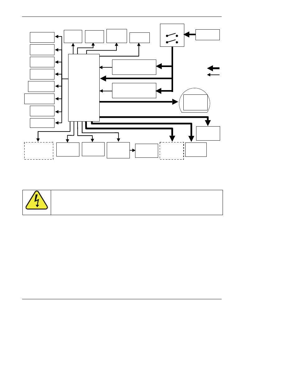
Figure 10-18: Power Distribution Block Diagram
A 6.75 ampere circuit breaker is built into the ON/OFF switch. In case of a wiring fault or incorrect
supply power, the circuit breaker will automatically turn off the analyzer.
CAUTION
Should the power circuit breaker trip correct the condition causing this
situation before turning the analyzer back on.
10.6. Communications Interface
The analyzer has several ways to communicate the with outside world, see Figure 10-19. Users
can input data and receive information directly through the front panel keypad and display. Direct,
two-way communication with the CPU is also available by way of the analyzer’s RS232 & RS485
I/O ports (see Section 6.10 and 6.12). Alternatively, an Ethernet communication option can be
substituted for one of the Comm ports.
The analyzer can also send status information and data via the eight digital status output lines
(see Section 6.12.1) and the three analog outputs (see Section 6.7) located on the rear panel as
well as receive commands by way of the six digital control inputs also located on the rear pane
(see Section 6.12.2).