Sensor module & sample chamber, Sample chamber heating circuit – Teledyne 6200E - Sulfides Analyzer User Manual
Page 221
Model 6200E Instruction Manual
Theory Of Operation
M6200E Rev: A1
221
In the unlikely event that the flash chip should fail, the analyzer will continue to operate with just
the DOC. However, all configuration information will be lost, requiring the unit to be recalibrated.
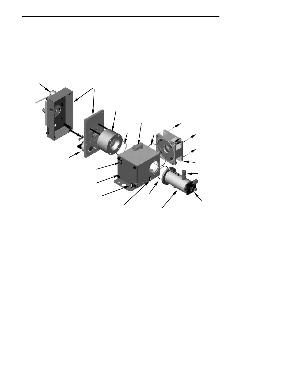
10.4.2. Sensor Module & Sample chamber
Electronically, the M6200E sensor module is a group of subassemblies with different tasks: to
detect the intensity of the light from the fluorescence reaction between H
2
S and O
3
in the sample
chamber, to produce a current signal proportional to the intensity of the fluorescence and to
control the temperature of the PMT cooler to ensure the accuracy and stability of the
measurements.
UV Source Lamp
Shutter Housing
Shutter Assy
(hidden from view)
UV Source Lens &
Housing
PMT Lens
Housing
Sample Chamber
Sample Chamber
Heater
Sample Chamber
Temperature Sensor
Reference
Detector
Light Trap
Sample Air
Outlet
O-Ring
Seal
Sample
Air Inlet
Sample Chamber
Heater
O-Ring
Seal
O-Ring
Seal
PMT
Housing
Attaches
Here
Figure 10-12: M6200E Sample Chamber
10.4.3. Sample Chamber Heating Circuit
In order to reduce temperature effects, the sample chamber is maintained at a constant 50°C,
just above the high end of the instrument’s operation temperature range. Two AC heaters, one
embedded into the top of the sample chamber, the other embedded directly below the reference
detector’s light trap, provide the heat source. These heaters operate off of the instrument’s main
AC power and are controlled by the CPU through a power relay on the relay board. A thermistor,
also embedded in the bottom of the sample chamber, reports the cell’s temperature to the CPU
through the thermistor interface circuitry of the motherboard.