Teledyne 6200E - Sulfides Analyzer User Manual
Page 141
Model 6200E Instruction Manual
Operating Instructions
M6200E Rev: A1
141
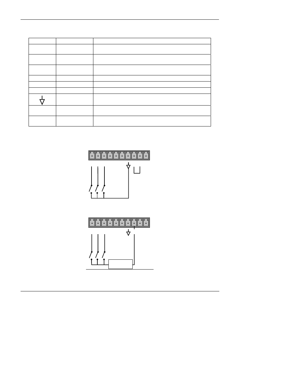
Table 6-23: Control Input Pin Assignments
INPUT
STATUS
CONDITION WHEN ENABLED
A
External Zero Cal Zero calibration mode is activated. The mode field of the
display will read ZERO CAL R.
B External
Span
Cal
Span calibration mode is activated. The mode field of the
display will read SPAN CAL R.
C
External Low
Span Cal
Low span (mid-point) calibration mode is activated. The mode
field of the display will read LO CAL R.
D
Unused
E
Unused
F
Unused
Digital Ground
Provided to ground an external device (e.g., recorder).
U
DC Power For
Input Pull Ups
Input for +5 VDC required to activate inputs A - F. This voltage
can be taken from an external source or from the “+” pin.
+
Internal +5v
Supply
Internal source of +5V which can be used to activate inputs
when connected to pin U.
There are two methods to activate control inputs. The internal +5V available from the “+” pin is
the most convenient method (Figure 6.18). However, to ensure that these inputs are truly isolated,
a separate, external 5 VDC power supply should be used (Figure 6.19).
CONTROL IN
A B C D E F U
+
LO
W
S
P
A
N
ZE
RO
SP
AN
Figure 6-18: Control Inputs with local 5 V power supply
CONTROL IN
-
+
5 VDC Power
Supply
LOW S
P
A
N
ZE
R
O
SP
A
N
A B C D E F U
+
Figure 6-19: Control Inputs with external 5 V power supply