2 æ 3, 2 æ 1 – Teledyne 6200E - Sulfides Analyzer User Manual
Page 37
Model 6200E Instruction Manual
Getting Started
M6200E Rev: A1
37
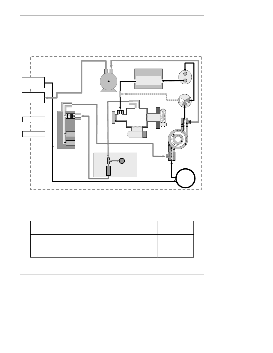
Figure 3-11 shows the internal pneumatic flow of the M6200E in its Standard configuration
For information on instruments in which one of the various zero/span valve options refer to
Figures 5-2 and 5-3.
Refer to these diagrams whenever trouble-shooting or a thorough understanding of the analyzer
performance are required.
PMT
EXHAUST THROUGH OUTER
LAYER OF KICKER
RE
AC
T
IO
N
CE
L
L
P
URG
E
FLOW
SENSOR
FLOW / PRESSURE
SENSOR PCA
SAMPLE
FILTER
INSTRUMENT CHASSIS
EXHAUST GAS
OUTLET
V
A
CUUM M
ANI
F
O
L
D
SAMPLE GAS
INLET
KICKER EXHAUST TO PUMP
PUMP
FLOW
CONTROL
ASSY
SAMPLE
PRESSURE
SENSOR
UV
LAMP
HYDROCARBON
SCRUBBER
(KICKER)
SPAN GAS INLET
ZERO AIR INLET
SAMPLE
CHAMBER
2
1
3
SO
2
Scrubber
MOLYBDENUM
CONVERTER
SO
2
Å H
2
S
H
2
S / SO
2
MODE VALVE
Gas Flow when multigas version of
M6200E analyzer is measuring SO
2
.
Figure 3-11: Pneumatic Diagram of the M6200E Standard Configuration.
Table 3-8: H
2
S – SO
2
Switching Valve Operating States
GAS
MODE
CONDITION OF H
2
S –SO
2
SWITCHING VALVE
VALVE PORT
CONNECTION
(FIG. 5-2)
H
2
S
Open to SO
2
Scrubber and Molybdenum Converter
2 Æ 3
SO
2
Open to directly to Sample Chamber. Bypasses SO
2
Scrubber and Molybdenum Converter
2 Æ 1
H
2
S –SO
2
Switches between above two states every 10 minutes.
- -