Flow rate control, Critical flow orifice – Teledyne 6200E - Sulfides Analyzer User Manual
Page 214
Theory Of Operation
Model 6200E Instruction Manual
214
M6200E Rev: A1
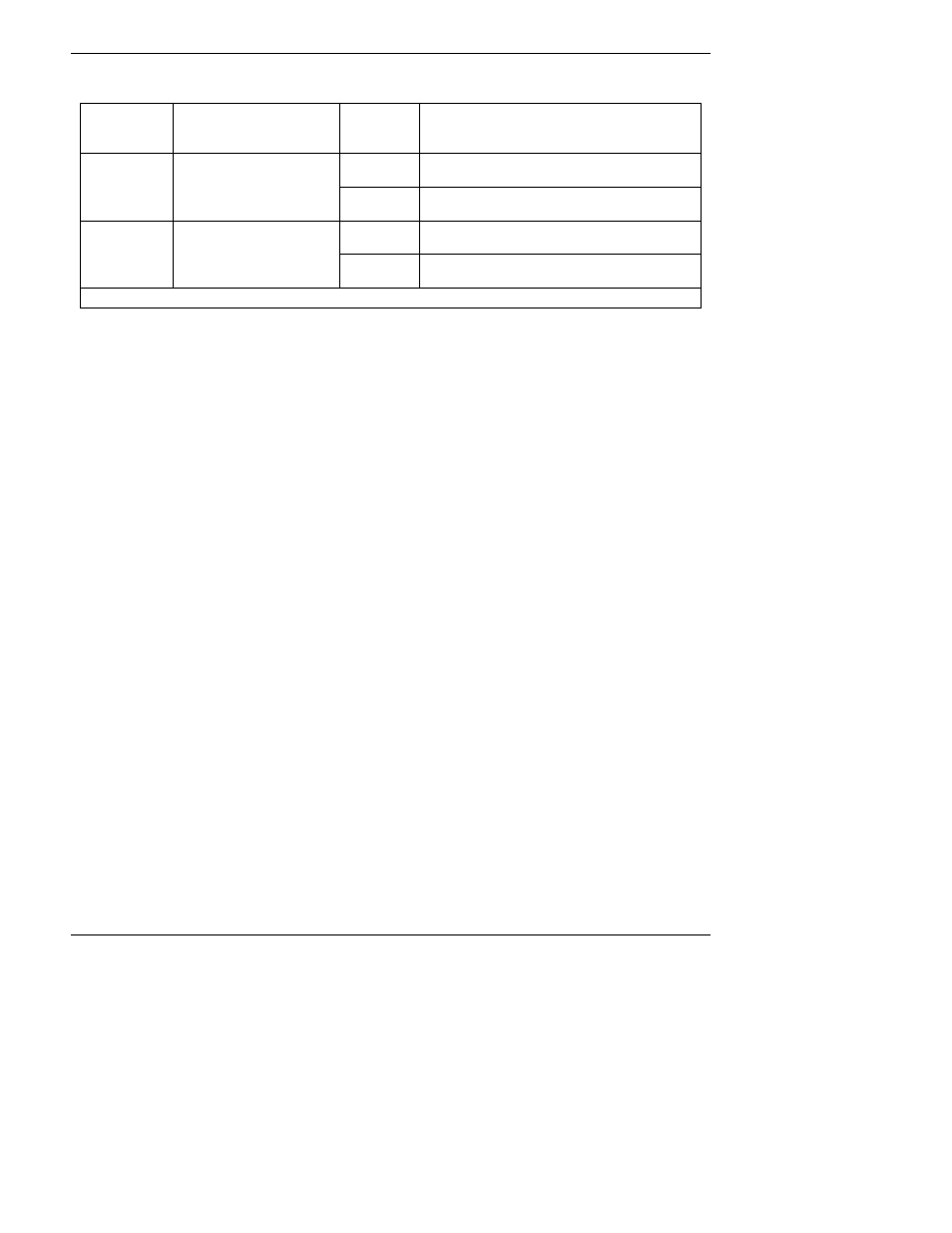
Table 10-1: M6200E Multigas Valve Cycle-Phases
Gas Mode
H
2
S
Æ SO
2
Valve Status
Default
Time
Settings
Activity
0 – 3
minutes
Wait period. Ensures sample chamber has
been flushed of previous gas.
H
2
S
Gas stream directed
through scrubber and
converter
3 – 10 m
Analyzer measures florescence in sample
chamber
0 – 3
minutes
Wait period (dwell time). Ensures sample
chamber has been flushed of previous gas.
SO
2
Gas stream bypasses
through scrubber and
converter
3 – 10 m
Analyzer measures florescence in sample
chamber
Cycle repeats every ~20Minuites
The timing of the above cycle is set by two variables (see Appendix A-2), MEASURE_PERIOD,
which sets the total dwell time for each gas mode, and MEASURE_DELAY which sets the wait
period before the instrument begins making measurements after the gas mode has been switch.
10.3.3. Flow Rate Control
The Model 6200E uses a special flow control assembly located in the exhaust vacuum manifold
(Figure 10-7) to maintain a constant flow rate of the sample gas through the instrument. This
assembly consists of:
A critical flow orifice.
Two o-rings: Located just before and after the critical flow orifice, the o-rings seal the gap
between the walls of assembly housing and the critical flow orifice.
A spring: Applies mechanical force needed to form the seal between the o-rings, the critical flow
orifice and the assembly housing.
10.3.3.1. Critical Flow Orifice
The most important component of this flow control assembly is the critical flow orifice.
Critical flow orifices are a remarkably simple way to regulate stable gas flow rates. They operate
without moving parts by taking advantage of the laws of fluid dynamics. By restricting the flow of
gas though the orifice, a pressure differential is created. This pressure differential combined with
the action of the analyzer’s external pump draws the gas through the orifice.
As the pressure on the downstream side of the orifice (the pump side) continues to drop, the
speed that the gas flows though the orifice continues to rise. Once the ratio of upstream pressure
to downstream pressure is greater than 2:1, the velocity of the gas through the orifice reaches
the speed of sound. As long as that ratio stays at least 2:1 the gas flow rate is unaffected by any
fluctuations, surges, or changes in downstream pressure because such variations only travel at
the speed of sound themselves and are therefore cancelled out by the sonic shockwave at the
downstream exit of the critical flow orifice.