Analog output voltages, Status outputs – Teledyne 6200E - Sulfides Analyzer User Manual
Page 256
TROUBLESHOOTING & REPAIR
Model 6200E Instruction Manual
256
M6200E Rev: A1
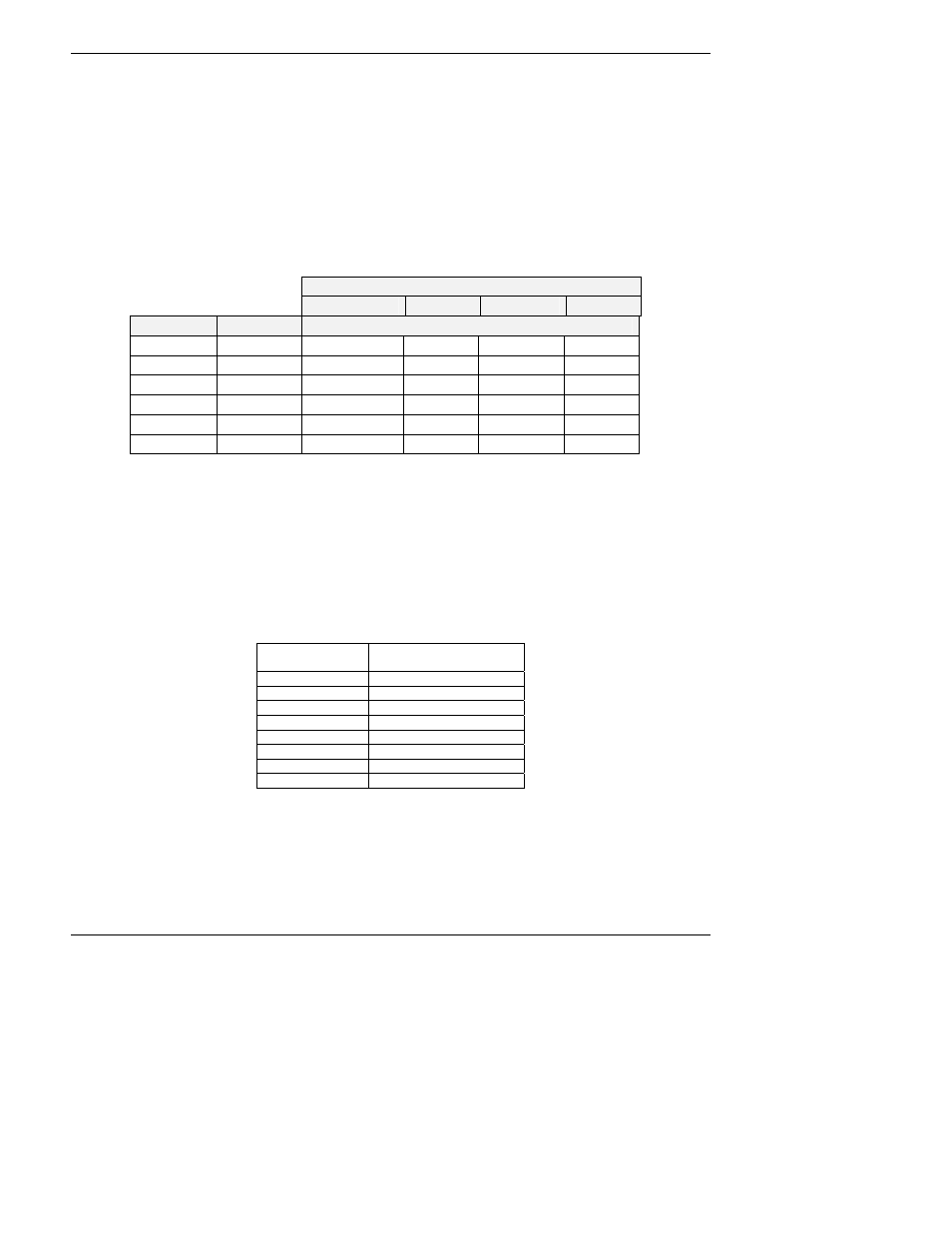
11.5.8.2. Analog Output Voltages
To verify that the analog outputs are working properly, connect a voltmeter to the output in
question and perform an analog output step test as described in Section 6.9.3.
For each of the steps, taking into account any offset that may have been programmed into the
channel (Section 6.9.4.4), the output should be within 1% of the nominal value listed in the table
below except for the 0% step, which should be within 2-3 mV. If one or more of the steps is
outside of this range, a failure of one or both D/A converters and their associated circuitry on the
motherboard is likely.
Table 11-7: Analog Output Test Function - Nominal Values
FULL SCALE OUTPUT VOLTAGE
100MV
1V
5V
10V
STEP
%
NOMINAL OUTPUT VOLTAGE
1 0 0
mV 0 0 0
2 20
20
mV
0.2
1 2
3 40
40
mV
0.4
2 4
4 60
60
mV
0.6
3 6
5 80
80
mV
0.8
4 8
6 100
100
mV
1.0 5 10
11.5.8.3. Status Outputs
The procedure below can be used to test the Status outputs.
1. Connect a cable jumper between the “-“ pin and the “V” pin on the status output connector.
2. Connect a 1000 Ω resistor between the +5 V and the pin for the status output that is being
tested.
Table 11-8: Status Outputs Check Pin Out
PIN
(left to right)
STATUS
1 System
Ok
2 Conc
Valid
3 High
Range
4 Zero
Cal
5 Span
Cal
6 Diag
Mode
7 Spare
8 Spare
3. Connect a voltmeter between the “-“ pin and the pin of the output being tested (Table 11-8).
4. Under the
DIAG / SIGNAL I/O menu (Section 6.9.2), scroll through the inputs and outputs
until you get to the output in question. Alternately turn on and off the output noting the
voltage on the voltmeter, it should vary between 0 volts for ON and 5 volts for OFF.