Cpu status indicator, Relay board status leds – Teledyne 6200E - Sulfides Analyzer User Manual
Page 245
Model 6200E Instruction Manual
TROUBLESHOOTING & REPAIR
M6200E Rev: A1
245
about once per second. If characters are written to the front panel display but DS5 does not flash
then the program files have become corrupted. Contact customer service because it may be
possible to recover operation of the analyzer. If, 30 - 60 seconds after a restart, DS5 is not
flashing and no characters have been written to the front panel display, the firmware may be
corrupted or the CPU may be defective. If DS5 is permanently off or permanently on, the CPU
board is likely locked up and the analyzer should not respond (either with locked-up or dark front
panel).
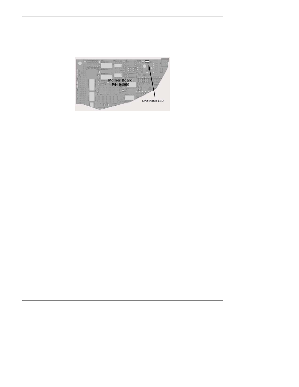
Figure 11-3: CPU Status Indicator
11.1.4.2. CPU Status Indicator
The CPU board has two red LEDs. LED1 is the upper-most LED and is a +5V power indicator, so it
should always be on. However, both CPU LEDs only indicate if the CPU is powered up properly and
generally working. The lower LED will sometimes be stable, and sometimes will blink. It can
continue to blink even if the CPU or firmware are locked up, and is not an effective indicator for
debugging system problems.
11.1.4.3. Relay Board Status LEDs
The most important status LED on the relay board is the red I
2
C Bus watch-dog LED, labeled
D1
(or W/D), which indicates the health of the I
2
C communications bus. This LED is located in the
upper left-hand corner of the relay board when looking at the electronic components. If D1 is
blinking, then the other LED’s can be used in conjunction with the
DIAG menu I/O functions to
test hardware functionality by switching devices on and off and watching the corresponding LED
go on or off. The LED only indicates that the logic signal for an output has been activated. If the
output driver (i.e. the relay or valve driver IC) is defective, then the LED will light up, but the
attached peripheral device will not turn on.