Available analog output signals, Figure 6-4: analog output connector key – Teledyne 6200E - Sulfides Analyzer User Manual
Page 70
Operating Instructions
Model 6200E Instruction Manual
70
M6200E Rev: A1
6.7. SETUP – RNGE: Analog Output Reporting Range
Configuration
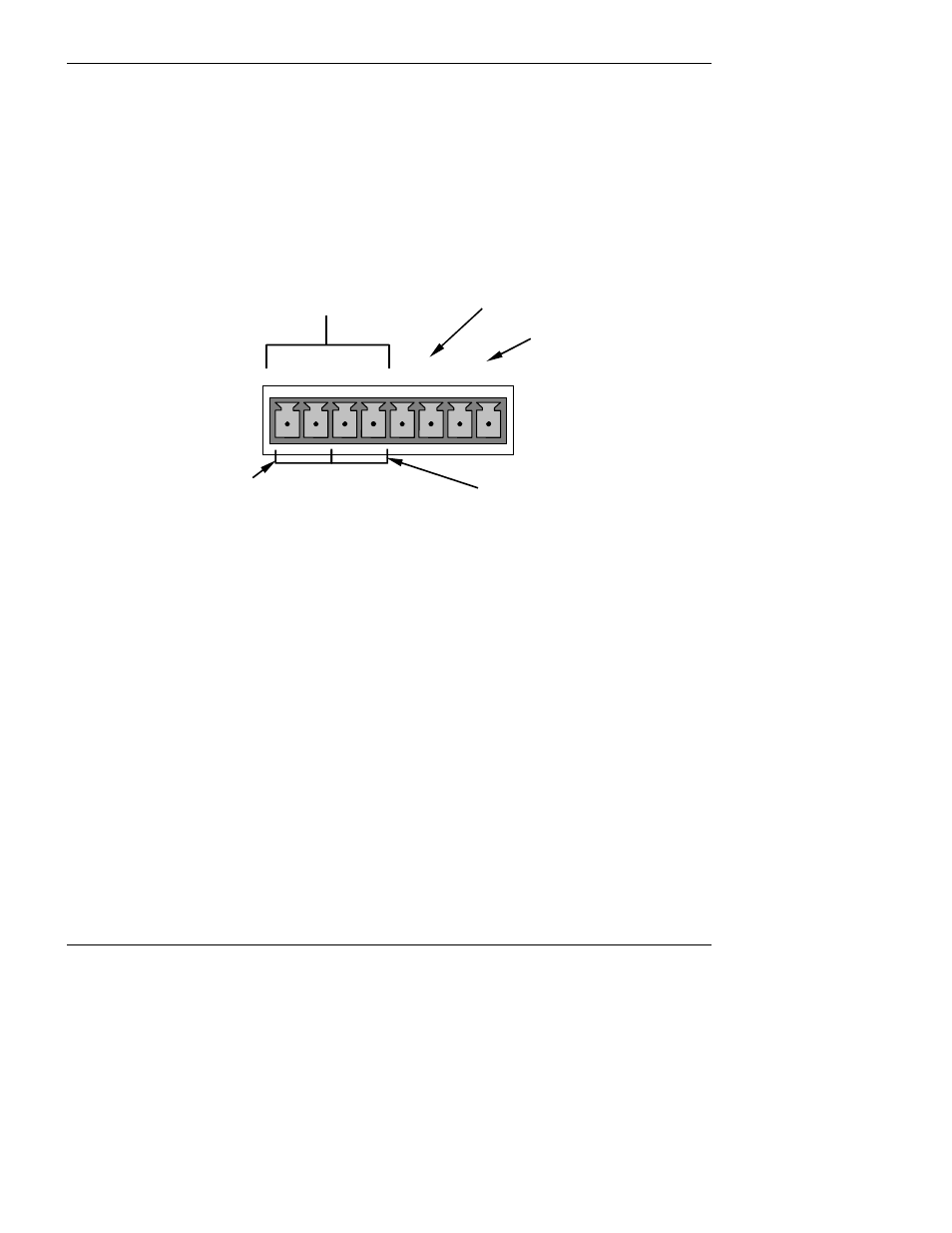
6.7.1. Available Analog Output Signals
The analyzer has three active analog output signals, accessible through a connector on the rear
panel.
ANALOG OUT
A1 A2 A3 A4
+ - + - + - + -
SO
2
concentration
outputs
HIGH range when
DUAL mode is selected
Not Used
Test Channel
LOW range when
DUAL mode is selected
Figure 6-4: Analog Output Connector Key
All three outputs can be configured either at the factory or by the user for full scale outputs of 0.1
VDC, 1VDC, 5VDC or 10VDC. Additionally A1 and A2 may be equipped with optional 0-20 mADC
current loop drivers and configured for any current output within that range (e.g. 0-20, 2-20, 4-20,
etc.). The user may also adjust the signal level and scaling of the actual output voltage or current
to match the input requirements of the recorder or datalogger (See Section 6.9.4.3 & 6.9.4.5).
In its basic configuration, the A1 and A2 channels of the M6200E output a signal that is
proportional to the H
2
S concentration of the sample gas. Several operating modes are available
which allow them to be slaved together (SNGL Mode, see Section 6.7.4 or AUTO mode, se section
6.7.6) or operate independently (IND mode, see Section 6.7.5) The user may also select between
a variety of reporting range spans as well:
EXAMPLE:
A1 OUTPUT: Output Signal = 0-5 VDC representing 0-1000 ppm concentration values
A2 OUTPUT: Output Signal = 0 – 10 VDC representing 0-500 ppm concentration values.