Pmt optical filter, Model 6200e instruction manual theory of operation, Into so – Teledyne 6200E - Sulfides Analyzer User Manual
Page 209: Figure 10-4), Figure 10-5: pmt optical filter bandwidth, Before after
Model 6200E Instruction Manual
Theory Of Operation
M6200E Rev: A1
209
LA
MP O
U
T
P
U
T
(A
rb
it
ra
ry
U
n
tis
)
10
5
10
4
10
2
2
0
2.
5
30
7.6
48
1.1
10
3
10
1
1
100 200 300 400 500
WAVELENGTH (nm)
0
213
.9
330
.3
275.
6
SO
2
*
Fluorescent
Spectrum
LAM
P
O
U
T
P
UT
(A
rb
it
ra
ry
U
n
ti
s
)
10
5
10
4
10
2
10
3
10
1
1
100
200
300
400
500
WAVELENGTH (nm)
0
213
.9
330
.3
SO
2
* FLUORESCENT
SPECTRUM
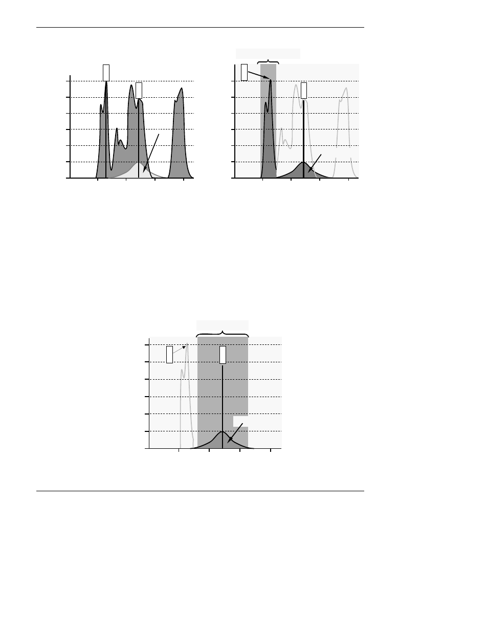
UV SOURCE OPTICAL FILTER
BANDWIDTH
BEFORE
AFTER
Figure 10-4: Excitation Lamp UV Spectrum Before/After Filtration
To solve this problem, the light emitted by the excitation UV lamp passes through a bandpass
filter that screens out photons with wavelengths outside the spectrum required to excite SO
2
into
SO
2
*. (Figure 10-4).
10.2.4.2. PMT Optical Filter
The PMT used in the Model 6200E reacts to a wide spectrum of light which includes much of the
visible spectrum and most of the UV spectrum. Even though the 214 nm light used to excite the
SO
2
is focused away from the PMT, some of it scatters in the direction of the PMT as it interacts
with the sample gas. A second optical bandpass filter placed between the sample chamber (see
Figure 10-2) and the PMT strips away light outside of the fluorescence spectrum of decaying SO
2
*
(see Figure 10-5) including reflected UV form the source lamp and other stray light.
LAM
P
OUT
P
UT
(A
rbi
trary
U
n
ti
s
)
10
5
10
4
10
2
10
3
10
1
1
100 200 300
400
500
WAVELENGTH (nm)
0
213.9
330.3
SO
2
* FLUORESCENT
SPECTRUM
PMT OPTICAL FILTER
BANDWIDTH
Figure 10-5: PMT Optical Filter Bandwidth