IAI America MSEP User Manual
Page 99
3.4 Fieldbus
Type
Address Map
91
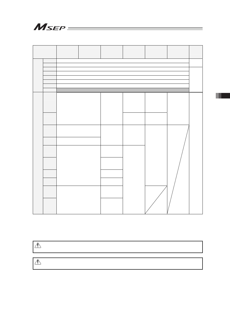
• MSEP Output ĺ PLC Input (n is PLC input top word address from MSEP)
(Note 1)
PLC Intput
Area
Simple Direct
Mode
Positioner 1
Mode
Direct
Indication
Mode
Positioner 2
Mode
Positioner 3
Mode
SEP I/O
Mode
(Note 2)
Details
n
Gateway Status 0
n+1
Gateway Status 1
3.4.3
n+2
Response Command
n+3
Data 0
n+4
Data 1
n+5
Data 2
n+6
Data 3
MSEP
Gateway
R
es
po
ns
e
Ar
ea
n+7
Occupied Domain
(Note 3)
3.4.9
n+8
Completed
Position No./
Simple Alarm
ID
(Axis No.0)
Status
Signal/
Completed
Position No.
(Axis No.0)
n+9
Current Position
(Axis No.0)
Current
Position
(Axis No.0)
Status Signal
(Axis No.0)
Assignment
Domain for
Axis No.1
Each axis
output port
number 0 to
4
(Axis No.0 to
7)
n+10
Completed Position No./
Simple Alarm ID
(Axis No.0)
n+11
Status Signal
(Axis No.0)
Command
Current
(Axis No.0)
Assignment
Domain for
Axis No.1
n+12
Current
Speed
(Axis No.0)
n+13
Occupied
Domain
(Axis No.0)
n+14
Alarm Code
(Axis No.0)
n+15
Assignment Domain for
Axis No.1
Status Signal
(Axis No.0)
Assignment
Domain for
Axis No.2 to
7
n+16 to
n+23
Assignment
Domain for
Axis No.1
C
on
ne
ct
ed
A
xe
s
R
es
po
ns
e
A
re
a
n+24 to
n+71
Assignment Domain for
Axis No.2 and later
Assignment
Domain for
Axis No.2
and later
Assignment
Domain for
Axis No.2
and later
3.4.4
to
3.4.8
Note 1 For CC-Link, n and n+1 are for input and output bit addresses, and n+8 is for the top
address of data register.
Note 2 SEP I/O Mode occupies 10 words no matter how many axes are connected.
Note 3 This is the domain occupied unconditionally. Therefore, this domain cannot be used for any
other purpose.
Caution: The mode can be selected for each slot, however, SEP I/O Mode cannot used
together with other modes.
Caution: For MECHATROLINK and CompoNet, only Positioner 3 Mode and SEP I/O Mode
are available for selection.